Stereoscopic image aligning apparatus, stereoscopic image aligning method, and program of the same

a technology of stereoscopic image and aligning apparatus, applied in the field of stereoscopic image aligning apparatus, can solve the problems of distorted captured images, inconvenient operation, and inability to accurately align the two image sensors (including the optical system) during manufacturing, so as to reduce the vertical parallax, the aspect ratio and the orthogonality of the viewing zone are preserved, and the time-consuming effect is shor

Inactive Publication Date: 2012-06-14
PANASONIC CORP
View PDF1 Cites 199 Cited by
  • Summary
  • Abstract
  • Description
  • Claims
  • Application Information

AI Technical Summary

Benefits of technology

[0045]A stereoscopic image aligning apparatus and the like can be provided which automatically align image pairs for stereoscopic viewing in a shorter amount of time than conventional apparatuses and which are applicable to image pairs captured by a single sensor camera or a variable baseline camera, without relying on camera parameters.
[0046]More specifically, since the processes can be automatically carried out according to the present invention, advantageous effects that surpass the conventional technique in PTL 2 are produced. In addition, the present invention does not rely on a calibration target and thus has advantage over the conventional technique in PTL 1. In addition, the present invention is designed for single sensor single sensor cameras and can also be applied for image pairs captured by variable baseline double sensor cameras and thus has advantageous effects that surpass the conventional technique in PTL 1 and PTL 3.
[0047]Another advantage is explained using FIG. 5a, FIG. 5b, and FIG. 5c. The method in PTL 4 aims to achieve alignment (rectification) with which the orientation of a camera and an image which are indicated as a left image 402 and a right image 404 in FIG. 5a is changed to the orientation indicated as a rectified left image 406 and a rectified right image 408 in FIG. 5b. Here, the epipoles are mapped to infinity and the epipolar lines are parallel to the horizontal axis. The present invention does not aim to achieve this. Instead, the present invention aims to achieve the alignment shown in FIG. 5c. Here, the vertical parallax is minimized, and the aspect ratio and orthogonality of the viewing zone is preserved (which will be explained in the embodiment). The right image 404 is transformed (warped) as indicated by a right image 410. According to the present invention, image transformation is performed on one of the left image and the right image rather than both of the left image and the right image. Therefore, the present invention has lower complexity over the conventional technique in PTL 4, and thus has the advantageous effect of reducing processing time.

Problems solved by technology

Unfortunately, the captured image pair is usually not well aligned (for many reasons).
For example, alignment of the two image sensors (including optical system) during manufacturing is not perfect.
Moreover, the captured images may be distorted due to lens distortion or camera configurations.
These can result in horizontal and vertical differences.
However, the main problem with this method is the misalignment of the left image and the right image, mainly due to hand movement when using handheld DSC (Digital Still Camera).

Method used


Image

  • Stereoscopic image aligning apparatus, stereoscopic image aligning method, and program of the same
  • Stereoscopic image aligning apparatus, stereoscopic image aligning method, and program of the same
  • Stereoscopic image aligning apparatus, stereoscopic image aligning method, and program of the same

Examples


Embodiment Construction

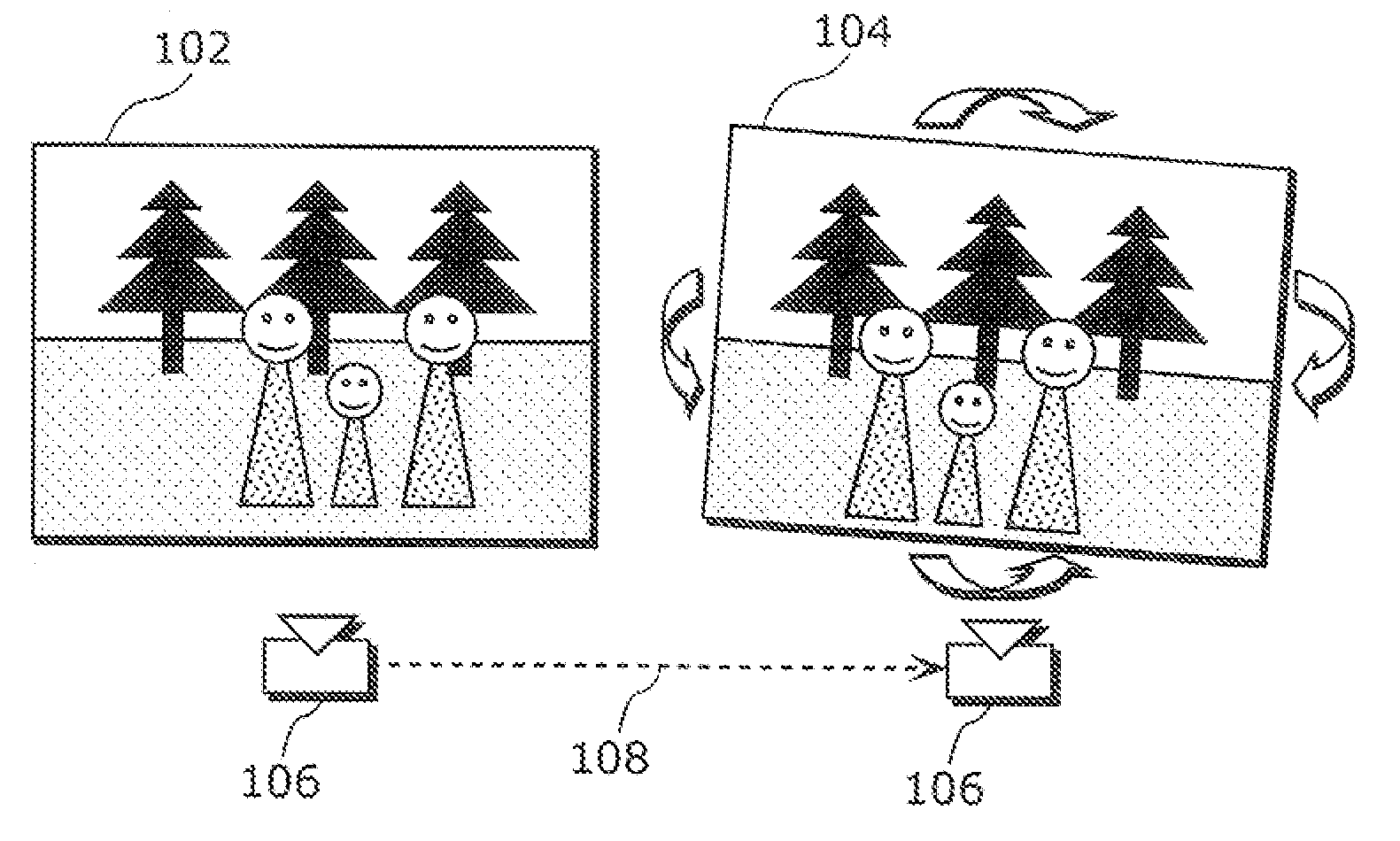
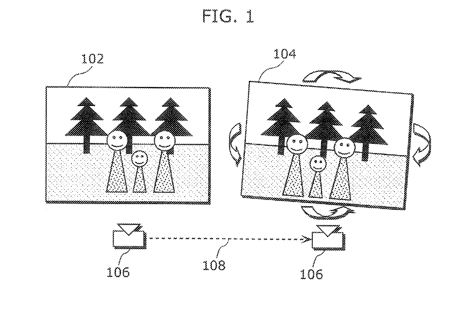
[0070]FIG. 1 shows an example for capturing an image pair using a single sensor capturing device; that is, an image capturing device that includes one lens and one image sensor. The left image 102 and the right image 104 are captured sequentially from different viewpoints using a single sensor digital camera 106. The camera moving distance between the left image 102 and the right image 104 is shown by a distance 108. It can be considered, in this example, that a user captures the left image 102 in a certain position and then moves his hand to the right by the distance 108 for capturing the right image 104.

[0071]In this example, the captured images (the left image 102 and the right image 104) are not aligned and contain the influence of translations and rotations due to camera movement (e.g. by hand). The distance 108 may be varied depending on the scene. For example, the distance 108 is shorter when the target object is closer and the distance 108 is larger when the target object is...


PUM


Abstract

A stereoscopic image aligning apparatus (200) automatically aligns image pairs for stereoscopic viewing in a shorter amount of time than conventional apparatuses, which is applicable to image pairs captured by a single sensor camera or a variable baseline camera, without relying on camera parameters. The stereoscopic image aligning apparatus (200) includes: an image pair obtaining unit (205) obtaining an image pair including a left-eye image and a right-eye image corresponding to the left-eye image; a corresponding point detecting unit (252) detecting a corresponding point representing a set of a first point included in a first image that is one of the images of the image pair and a second point included in a second image that is the other of the images of the image pair and corresponding to the first point; a first matrix computing unit (254) computing a homography transformation matrix for transforming the first point such that a vertical parallax between the first and second points is smallest and an epipolar constraint is satisfied; a transforming unit (260) transforming the first image using the homography transformation matrix; and an output unit (210) outputting: a third image that is the transformed first image; and the second image.

Description

TECHNICAL FIELD [0001]The present invention relates to stereoscopic image aligning apparatuses which detect corresponding points from plural image pairs and align the detected corresponding points to meet a certain criterion. The present invention relates particularly to a stereoscopic image aligning apparatus and the like, which aligns an image pair to allow stereoscopic viewing on a stereoscopic display device.BACKGROUND ART [0002]Stereoscopic imaging has been studied for many years in the art. Stereoscopic images allow the perception of depth so to bring viewers with the presence feeling, which has become a hot and promising topic now for home entertainment industry. Stereoscopic imaging is also widely used in applications ranging from military navigation, medical imaging, industrial inspection, to consumer electronics, etc. The principles of stereoscopic imaging and displays are well known. To be specific, each of a left-eye image and a right-eye image which constitute an image ...

Claims


Application Information

Patent Timeline
Patent Type & Authority Applications(United States)
IPC IPC(8): H04N13/00H04N13/128
CPCG03B35/08H04N13/0007H04N13/0018H04N13/0022H04N2013/0074H04N13/0239H04N13/026H04N13/0475H04N13/0221H04N13/106H04N13/128H04N13/261H04N13/373H04N13/239H04N13/221H04N13/122
Inventor LI, BOLASANG, PONGSAKONG, CHIN PHEKSHEN, SHENG MEITAGAWA, JUNICHI
Owner PANASONIC CORP
Why Eureka
Try Eureka