
Video Transmission On A Serial Interface

a serial interface and video technology, applied in the field of circuits and methods for transmitting video signals, can solve the problems of not allowing data transmission to be synchronized on a clock, unable to control the transmission rate of serial interfaces, and unable to achieve clock synchronization

Inactive Publication Date: 2012-06-14
OPTIS CIRCUIT TECH LLC
View PDF5 Cites 18 Cited by
  • Summary
  • Abstract
  • Description
  • Claims
  • Application Information

AI Technical Summary

Benefits of technology

[0008]An object of embodiments of the present invention is to a...

Problems solved by technology

However, there is a problem in controlling the transmission rate on a serial interface.
However, a disadvantage of this solution is that it does not allow the data transmission to be synchronized on a clock different from the one used to synchronize the display.
Further, in certain embodiments, it is desirable for two displays to be driven via a hub, while using the same serial interface, which is not possible with this solution.
A disadvantage of this solution is that it requires a relatively large buffer on the receive side to store the image data before display.
Further, if two displays are desired to be driven via a hub while using the same serial interface, there is also a problem in efficiently synchronizing the flow of the two packet streams on their respective display, and a problem of efficiency and flow management between the input and the output of the hub.

Method used


Image

  • Video Transmission On A Serial Interface
  • Video Transmission On A Serial Interface
  • Video Transmission On A Serial Interface

Examples


Embodiment Construction

[0060]In the drawings, the same features have been designated with the same reference numerals.

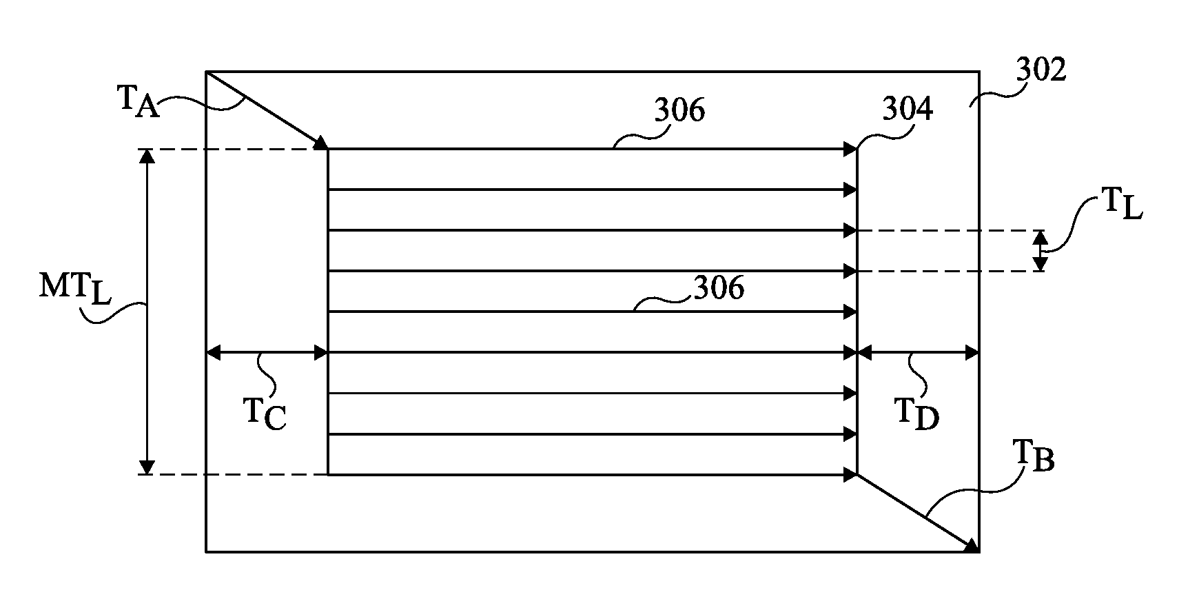
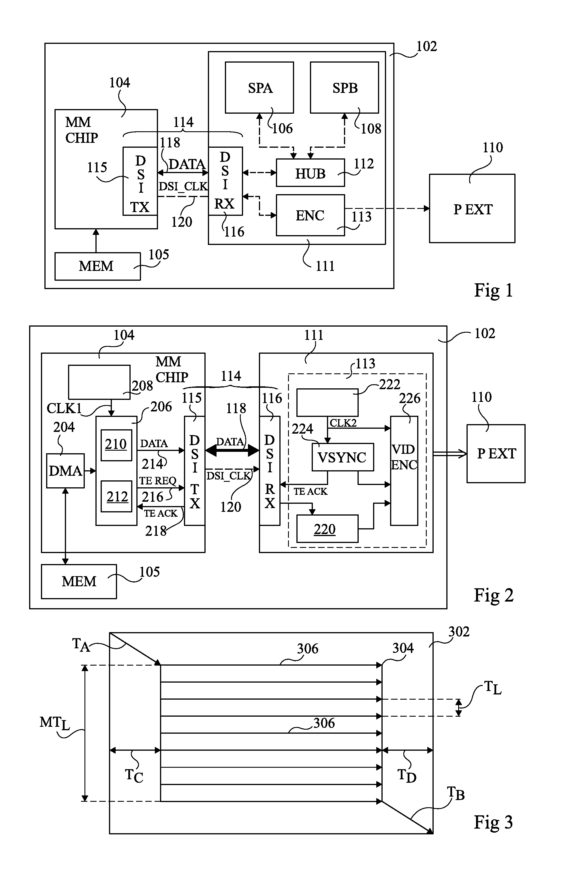
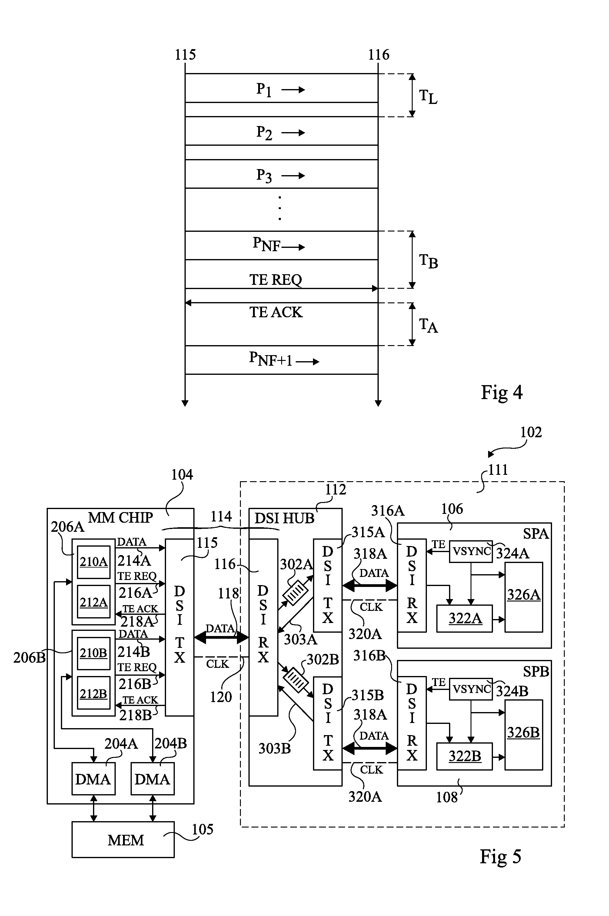
[0061]FIG. 1 shows a portable electronics device 102, which is for example, a cell phone, a smartphone, a laptop computer, a portable game console, or another electronics device. Device 102 comprises a multimedia chip 104 (MM CHIP), which is for example the processing platform of the portable device. Chip 104 is coupled to a memory 105 (MEM) of the device, from which data to be displayed on one or more integrated or external displays can be retrieved. For example, device 102 comprises one or more integrated displays 106 (SPA), 108 (SPB), and / or may be connected to an external display panel 110 (P EXT).

[0062]The video data is provided by chip 104 to a receive circuit 111, which comprises one or both of displays 106, 108 coupled to a serial interface hub 112 and / or an encoding circuit 114, for formatting the video signal so that it is suitable for an external transmission to display 110.

[006...


PUM


Abstract

A video transmission circuit for transmitting video data on a digital serial interface to a receive circuit arranged to process the video data at a constant rate, the circuit including a transmission block comprising: a packet generator arranged to generate, for each image of the video data, a plurality of packets, each containing a pixel group of the image; a transmit circuit arranged to transmit the packets of each image on a digital serial interface at time intervals based on the constant rate; and a synchronization circuit arranged to receive from the receive circuit, after transmission of a plurality of packets, a synchronization signal for synchronizing the beginning of the transmission of a next packet.

Description

BACKGROUND OF THE INVENTION[0001]1. Field of the Invention[0002]The present invention relates to a circuit and a method for transmitting video signals, and in particular to a circuit and a method for transmitting video data on a digital serial interface.[0003]2. Discussion of the Related Art[0004]Portable electronic devices often comprise integrated display panels and / or the capability of providing a video signal to an external display panel such as an LCD (liquid crystal display), plasma, or OLED (organic light-emitting diode) display.[0005]Generally, in such devices, a main processor retrieves video images from a memory. The images can then be directly transmitted from the main processor to an integrated display of the portable device or, if the video signal is to be transmitted to an external display, they may be provided to a video encoder which puts the video images in a format appropriate for external transmission. It is desirable for the internal displays and / or the video enc...

Claims


Application Information

Patent Timeline
IPC IPC(8): H04N7/56H04N5/06
CPCG09G2370/10G09G5/006G09G2370/12
Inventor RIES, GILLES
Owner OPTIS CIRCUIT TECH LLC
Learn More