Extraction Fan Assembly for an Animal Husbandry Barn

a technology for extracting fans and animal husbandry, which is applied in the direction of domestic heating details, space heating and ventilation details, heating types, etc., can solve the problem that pathogens can still enter the containment area, and achieve the effect of preventing air back-draft pathogen contamination, reducing the ventilation rate, and improving the air quality

Inactive Publication Date: 2012-06-14
LABRECQUE ROBERT
View PDF12 Cites 10 Cited by
  • Summary
  • Abstract
  • Description
  • Claims
  • Application Information

AI Technical Summary

Benefits of technology

[0044]Thus the flap and the pin action control the minimum ventilation rate for the fan when the fan faces wind forces. This can be used both in air-filtered barns and even for barns without air filters.
[0045]The addition of the pin at the bottom of the panel is used in order to be able to keep a continuous minimum opening which can vary from 0.5 to 6 inch according to the remote adjustment of the pin. Then, even if the slow running fan faces a lot of wind, the damper will stay open and the air can be easily blown out by the fan, preventing air back-draft pathogen contamination in air-filtered barns. In the case of barns that are not air-filtered, the objective is not to prevent virus transmission but only to control the minimum ventilation rates even with or without windy conditions. The purpose is to improve the air quality inside the barn even if winds faces the fans. This will allow an easy minimum ventilation rates adjustment for the operators and reduced energy cost for fan operation and building heating.
[0046]In order to have a better minimum ventilation rate control, the standard louvers installed on the fan can be removed.
[0

Problems solved by technology

However it is known that pathogens can still enter the containment area by the fans louvers and disease can still strike, often with very damaging results.
However it is known that pathogens can still enter the containment area through closed fans louvers, due to known negative air pressure (0.05 inch of water) inside the building.
It has been experimented that a 24″ fan tha

Method used


Image

  • Extraction Fan Assembly for an Animal Husbandry Barn
  • Extraction Fan Assembly for an Animal Husbandry Barn
  • Extraction Fan Assembly for an Animal Husbandry Barn

Examples


Embodiment Construction

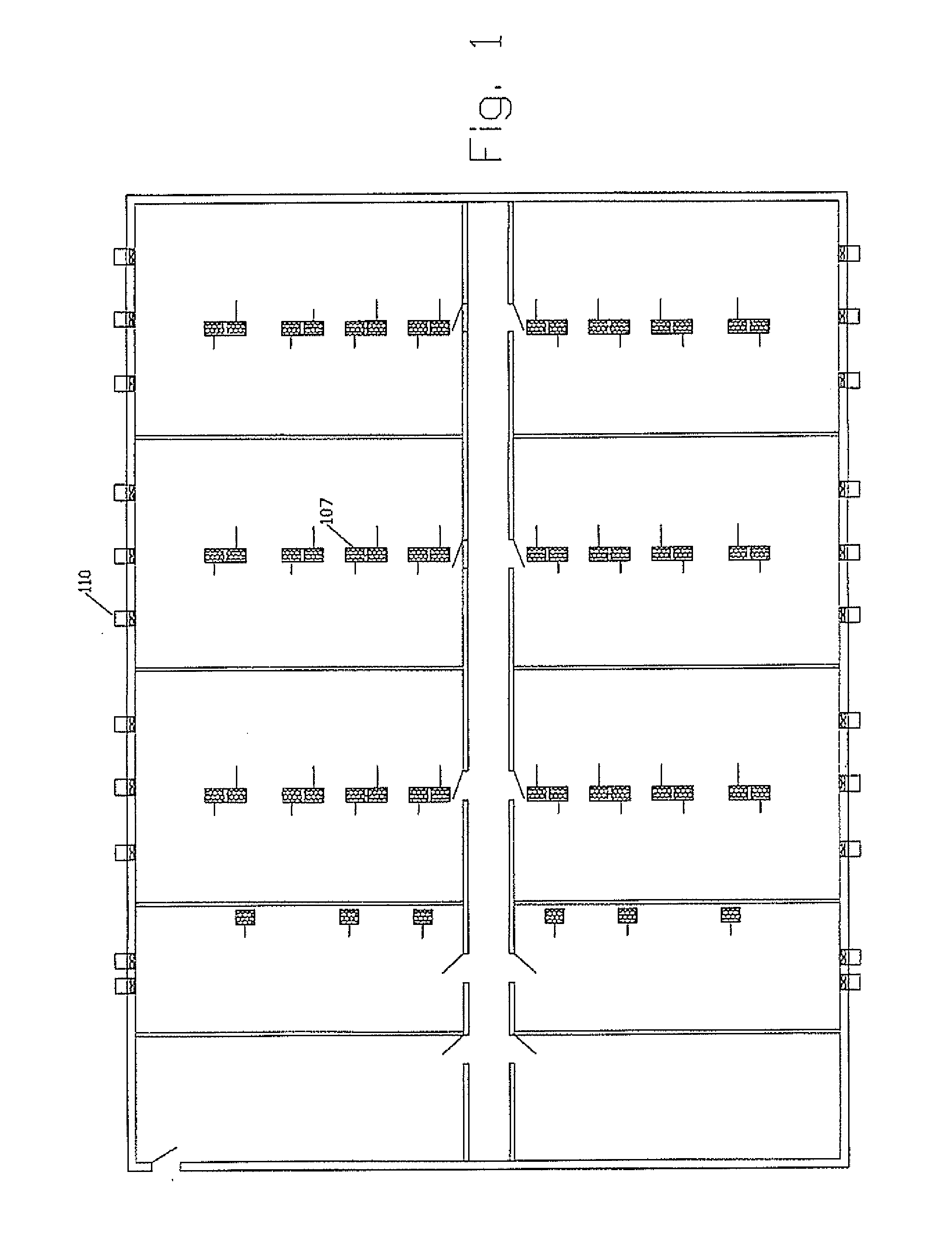
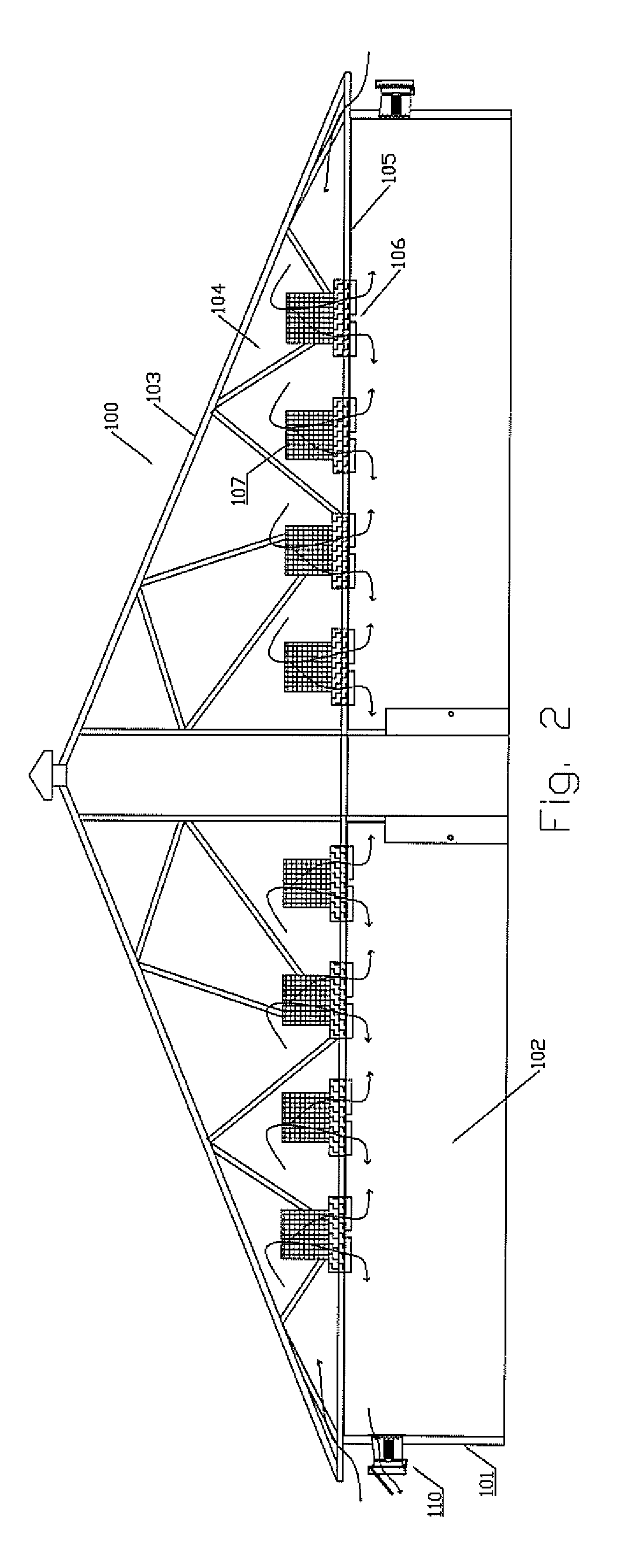
[0061]In FIGS. 1 and 2 is shown an animal husbandry barn 100 including peripheral walls 101 defining a containment area 102. A roof 103 defines a roof space 104 above a ceiling 105.

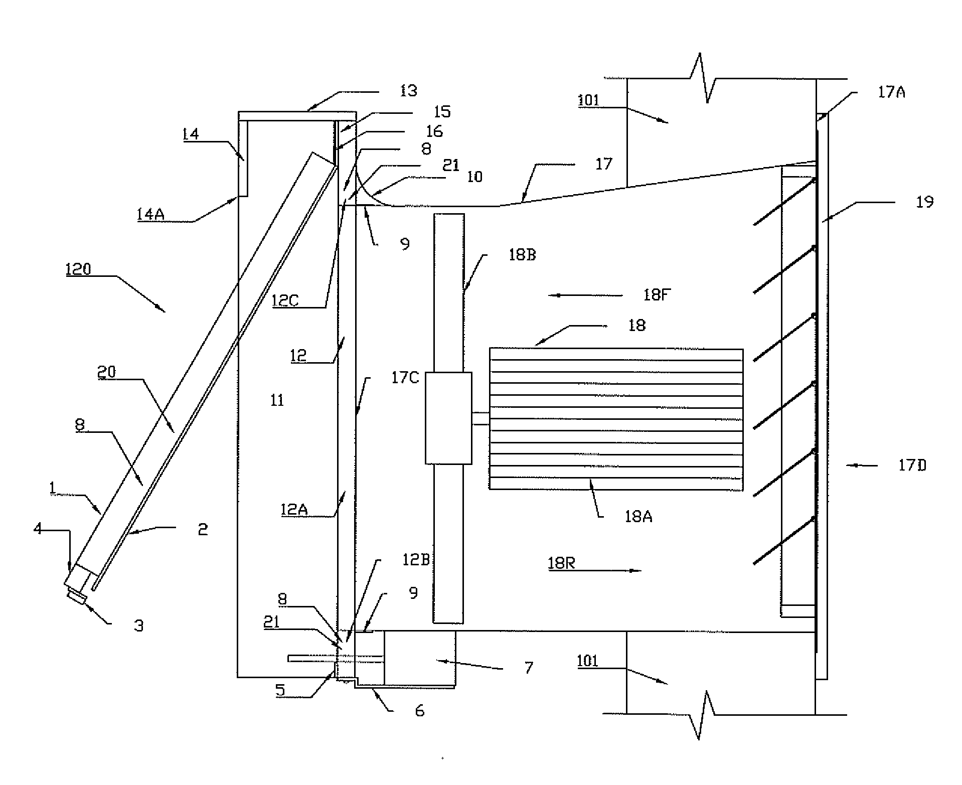
[0062]A plurality of air inlets 106 provide air entry into the containment area where each air inlet 106 has an air filter system 107 for extraction from incoming air of pathogens so as to prevent transmission of disease to the animals.

[0063]A plurality of extraction fans 110 are located at spaced positions around the walls for generating an air stream exiting the containment area so as to generate a negative air pressure within the barn so as draw replacement air into the containment area through the air inlets 106. Apart from the inlets and the extraction fans, the containment area is sealed against ingress of pathogen containing air.

[0064]The extraction fans can be driven at variable rate including at least high and low speed and can be shut off when not required. Shutting off fans when possible of cou...


PUM


Abstract

An animal barn includes air inlets which are filtered to extract pathogens and a plurality of extraction fans for generating an air stream so as to draw replacement air into the containment area through the air inlets. Each fan has a housing mounted in a wall with an outlet duct extending through the wall to an outlet opening outside the wall. A damper flap is mounted on the fan suspended by a hinge at an upper edge so as to extend in a closed position across the opening in a mounting plate. The damper flap is movable to an open position under forward air flow from the fan and closes against a resilient deformable seal to seal the damper flap to prevent reverse flow of pathogen contaminated air through the fan housing when the fan is shut off. An adjustable abutment member can act to hold the flap partly open against opposing wind forces during low fan operation.

Description

[0001]This invention relates to a fan construction for use in an animal husbandry barn.[0002]Typically such barns comprise a containment area; a plurality of air inlets into the containment area and a plurality of extraction fan constructions for generating an air stream exiting the containment area so as to draw replacement air into the containment area through the air inlets. In many cases each air inlet has an air filter system for extraction from incoming air of pathogens so as to reduce transmission of disease to the animalsBACKGROUND OF THE INVENTION[0003]In recent years prevention of disease to animal husbandry barns has reached the extent where attempts are made to ensure that all air entering the barn is filtered of pathogens that can be airborne. For this reason a number of companies provide systems for filtering the air at the intakes. Typically the air intakes communicate with the roof space with the air entering into the containment area through the ceiling and also fro...

Claims


Application Information

Patent Timeline
IPC IPC(8): F24F7/013F24F13/08
CPCF24F13/14F24F13/1486A01K1/0052F24F7/013F04D25/08F04D25/14A01K1/0064
Inventor LABRECQUE, ROBERT
Owner LABRECQUE ROBERT
Why Eureka
Try Eureka