
Eureka
For R&D, Eureka makes reading and utilizing patents & technical documents easy.
Eureka AIR
Designed for self-driven R&D workflows. Generate viable solutions, solve complex R&D challenges, empower your innovation with AI.

Eureka Materials
Designed for material experts only. Revolutionize your material R&D, from search, analyze, to developing new materials.

TechResearch
Generate reliable direction feasibility study reports for your R&D in just a few steps.

TechSeek
Discover and master advanced knowledge NOW. Basics, ideas, possibilities, all at once.

TechMind
As an expert in R&D Theories, TechMind can generates customized viable solutions instantly.

TechRisk
Analyze your overall solution with one click, know your potential R&D risks in advance.

TechMonitor
Get weekly tech updates, stay abreast of the latest tech innovations and key insights.
Particulate matter detection sensor
- Summary
- Abstract
- Description
- Claims
- Application Information
AI Technical Summary
Benefits of technology
Problems solved by technology
Method used
Image

Examples
first exemplary embodiment
[0049]A description will be given of the particulate matter detection sensor (PM detection sensor) according to a first exemplary embodiment of the present invention with reference to FIG. 1A to FIG. 3B.
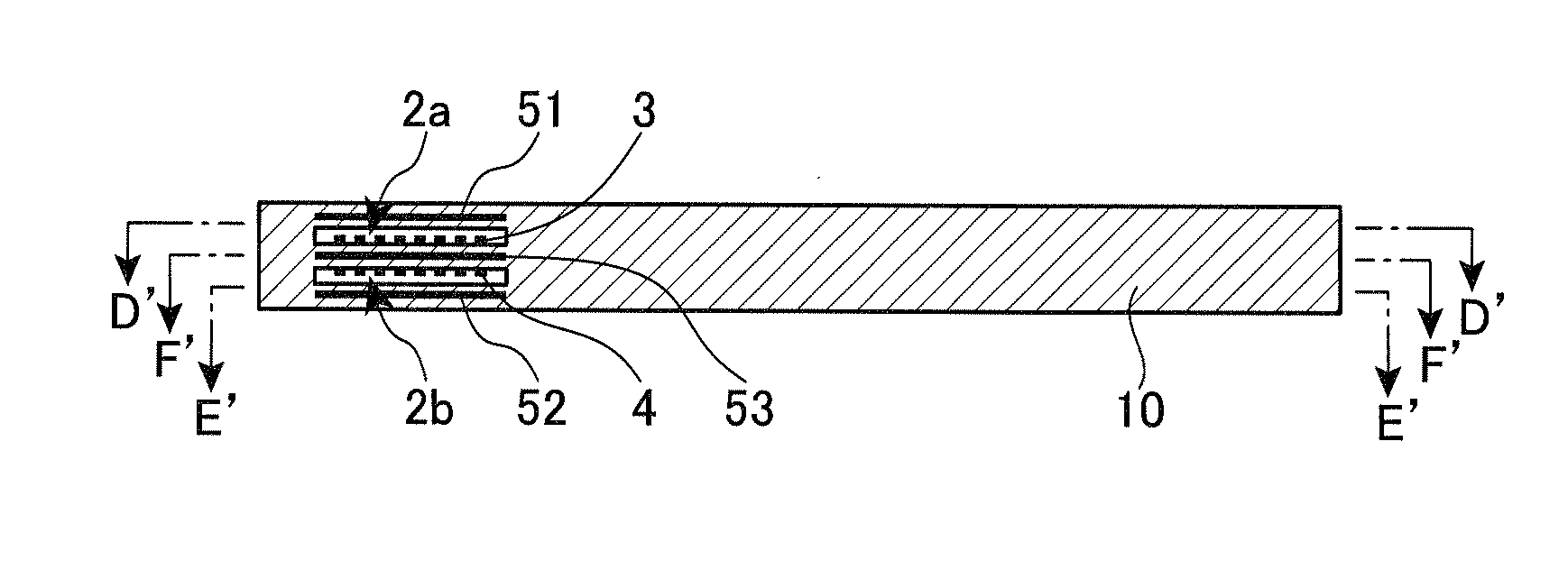
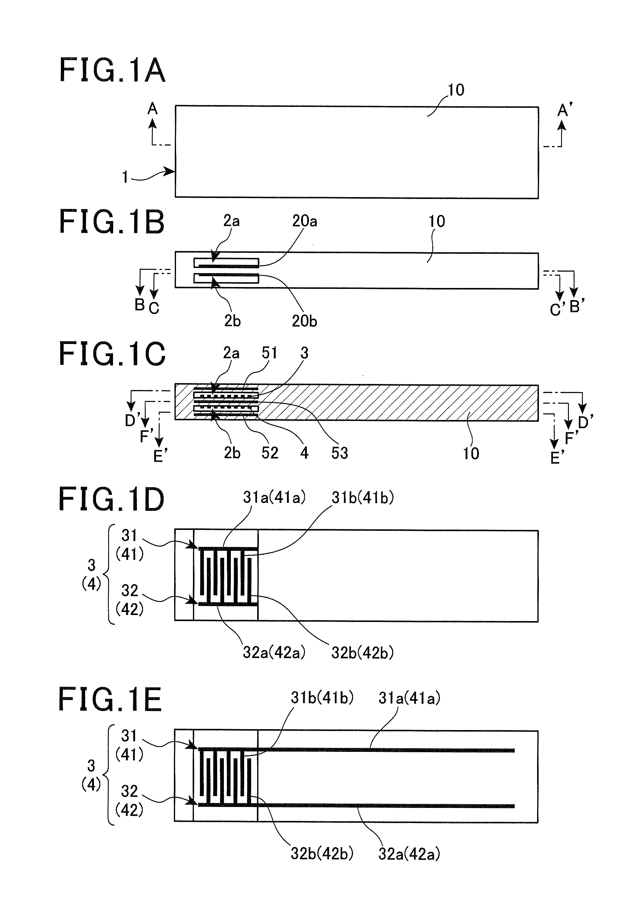
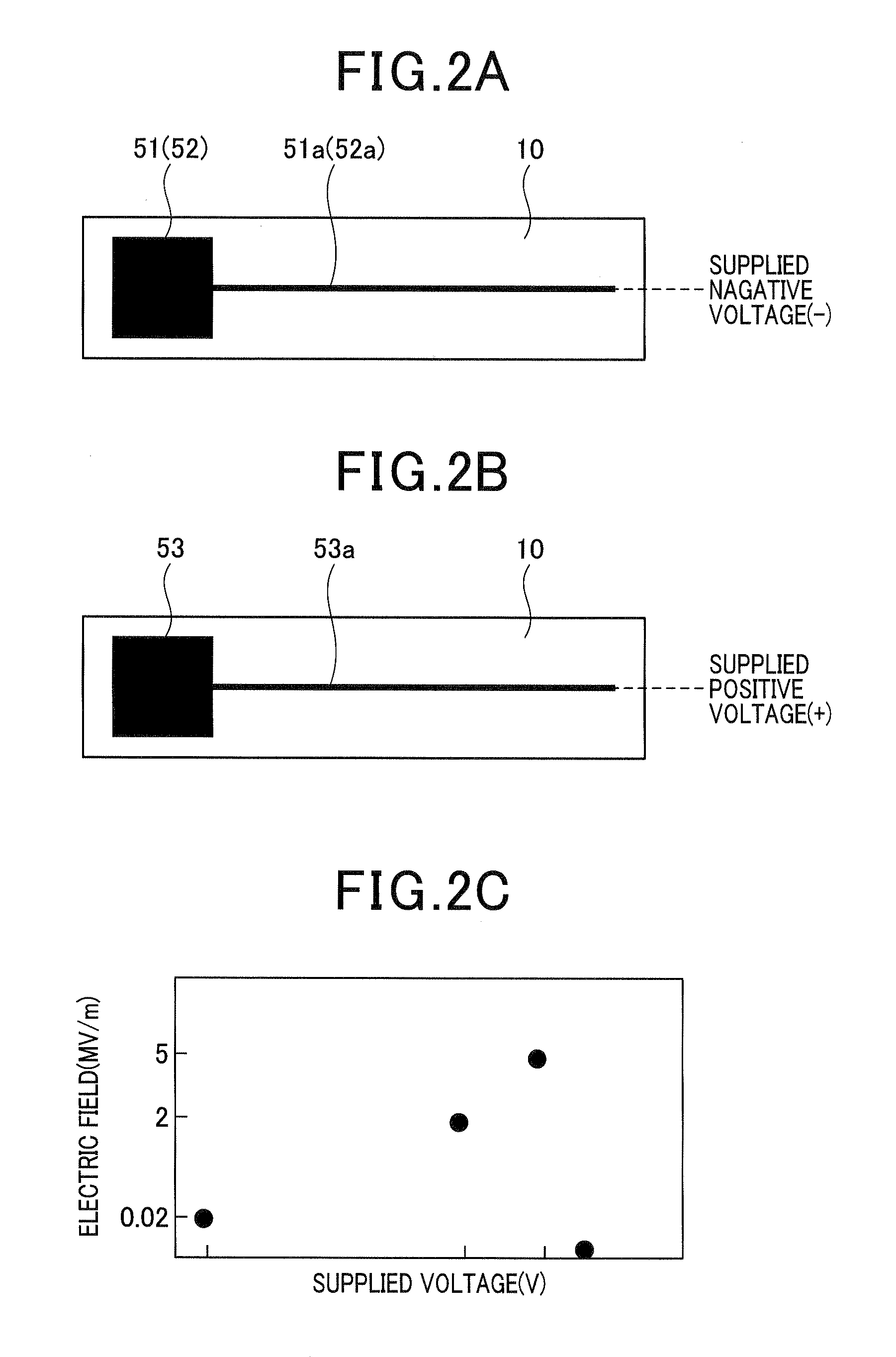
[0050]FIG. 1A to FIG. 1E show a schematic structure of a PM sensor element 1 in the PM detection sensor S according to an exemplary embodiment of the present invention. The PM sensor element 1 is a main component of the PM detection sensor S. FIG. 2A to FIG. 2C show a schematic action of the PM sensor element 1 in the PM detection sensor S.
[0051]FIG. 3A is an enlarged cross section showing a state in which the PM detection sensor S is installed into an exhaust gas pipe in an exhaust gas purifying system for a motor vehicle diesel engine diesel engine (E / G) system. FIG. 3B is a schematic view showing an entire structure of the exhaust gas purifying system for the motor vehicle E / G system to which the PM detection sensor S according to the exemplary embodiment is installed.
[0052]The di...
second exemplary embodiment
[0096]A description will be given of a PM sensor element 1-1 according to a second exemplary embodiment of the present invention.
[0097]FIG. 5 is an exploded view showing the PM sensor element in the PM sensor element 1-1 according to the second exemplary embodiment of the present invention.
[0098]The PM sensor element 1-1 according to the second exemplary embodiment has a heater part 6 in addition to the structure of the PM sensor element 1 according to the first exemplary embodiment shown in FIG. 1A to FIG. 1E. That is, components of the PM sensor element 1-1 other than the heater part 6 shown in FIG. 5 are the same of the components of the PM sensor element 1 shown in FIG. 1A to FIG. 1E. The heater part 6 in the PM sensor element 1-1 will be explained.
[0099]The insulation substrate 10 in the PM sensor element 1-1 has the slits 20a and 20b corresponding to the detection spaces 2a and 2b, insulation layers 11 to 17 in which the pair of the PM detection electrodes 3 and 4 and the elec...
first experiment
(First Experiment)
[0116]The first element and the second element were placed in an exhaust gas pipe communicate with a diesel engine. Through the exhaust gas pipe, exhaust gas emitted from the diesel engine is discharged to the outside. During the working of the internal combustion engine, the first experiment detected the sensor output obtained from each of the first element and the second element during a predetermined period of time. The sensor output of the first element corresponds to the change in electric resistance between the electrodes of the PM detection electrode 3. The sensor output of the second element corresponds to the change in electric resistance between the electrodes in each of the PM detection electrodes 3 and 4.
[0117]The first experiment was repeated three times. FIG. 7A and FIG. 7B show the experimental results. The quantity of PM contained in exhaust gas was detected by a PM analyzer. The slit 20 formed in the first element is equal in size to each of the sl...
PUM
 Abstract
Description
Claims
Application Information
 - R&D Engineer
- R&D Manager
- IP Professional
- Industry Leading Data Capabilities
- Powerful AI technology
- Patent DNA Extraction
Browse by: Latest US Patents, China's latest patents, Technical Efficacy Thesaurus, Application Domain, Technology Topic, Popular Technical Reports.
© 2024 PatSnap. All rights reserved.Legal|Privacy policy|Modern Slavery Act Transparency Statement|Sitemap|About US| Contact US: help@patsnap.com