Heat exchange apparatus

a heat exchange apparatus and heat exchange technology, applied in indirect heat exchangers, lighting and heating apparatus, transportation and packaging, etc., can solve the problems of reducing the output of wanted side products, requiring expensive further processing to remove unwanted products or products, and affecting the efficiency of heat exchange, so as to achieve the effect of improving the rate of heat exchang

Inactive Publication Date: 2012-06-21
HOLL RICHARD A
View PDF2 Cites 3 Cited by
  • Summary
  • Abstract
  • Description
  • Claims
  • Application Information

AI Technical Summary

Benefits of technology

[0008]It is a principal object of this invention to provide new heat exchange apparatus providing enhanced rates of heat exchange and particularly, but not exclusively, to provide such apparatus which can readily be combined with spinning tube in tube reactors, and even more particularly, but not exclusively, which can readily be incorporated with spinning tube in tube micro reactors.
[0010]It is a further object to provide new heat exchange apparatus and particularly, but not exclusively, to provide such apparatus which can readily be incorporated with spinning tube in tube reactors, and even more particularly, but not exclusively, which can readily be incorporated with spinning tube in tube micro reactors, in which minimization of the thickness of the boundary layer in the heat exchanger flow passages is produced by the structure of the heat exchanger, with the consequent possibility of increase of efficiency of the heat exchanger.
[0015]the apparatus also comprising means for moving the heat exchange fluid through the flow passage at a flow rate such that its velocity, at least in the throttle forming portions, is high enough to reduce the thickness of the heat exchange fluid boundary layer in the throttle portions, and thereby facilitate heat exchange from the heat exchange fluid to the one wall surface.
[0016]Alternatively, or in addition, the apparatus comprises means for moving the heat exchange fluid through the flow passage at a flow rate such that its velocity, at least in the throttle forming portions, is high enough to at least reduce the rate of fouling of the one wall surface.
[0017]Alternatively, or in addition, the apparatus also comprises means for moving the heat exchange fluid through the flow passage at a flow rate such that the heat exchange fluid flows in the flow passage chamber portions as laminar eddies contacting the one wall surface, and that the spacing of the flow passage chamber portions along the flow passage is such that wake interference flow is established in the flow passage to thereby enhance the rate of heat exchange between the heat exchange fluid and the one wall surface.

Problems solved by technology

Variations in the temperature outside this range can, for example, cause unwanted side reactions to occur, reducing the output of the wanted side product, and often requiring expensive further processing to remove the unwanted product or products.
Typically the initial stirring shows bulk interaction taking place very quickly, for example within minutes, but interaction then slows considerably and satisfactory mixing may take several days to accomplish.
One phenomenon that inhibits quick inter-dispersion is that the reagents in the bulk liquid inevitably are in the form of discrete bodies thereof, these bodies comprising what are known as Kolmogoroff smallest eddies or vortices, of dimension usually about 15-30 microns, which considerably reduce the possibility of the desired one-on-one molecular contact.
Consequently, inside such Kolmogoroff eddies, only natural molecular diffusion can accomplish such one-on-one contact, which is a very slow process.
It is of course possible to provide heat exchange means within the rotor with its wall as the corresponding heat exchange member, but this introduces practical difficulties of feeding the heat exchange fluid to the interior of the hollow rotating rotor without leakage, and removing it therefrom.
A phenomenon that can deleteriously affect the rate of heat transfer from a heat exchanger to its associated apparatus is that its flow passage or passages inherently have at the surfaces of their intervening walls a stationary layer of the heat exchange fluid through which the exchanging heat must pass.
The problem involved is to obtain successive continuous interruptions in the fluid flow without producing a flow that will increase the pumping pressure to an uneconomical value.
A constant problem with heat exchangers is the tendency for material from the heat exchange fluid to deposit on the walls of the heat exchange passage in which it is flowing.
This material, however it originates, is generically referred to as “fouling material” and is deleterious to optimum operation of the heat exchanger by reducing the flow capacity of the heat exchange passage, and by reducing the rate of transfer of heat between the heat exchanger and the reactor through the intervening wall coated with the fouling material.
The problem is especially difficult in heat exchangers employed with micro reactors owing to the necessarily small dimensions of the passages, so that the particles of fouling material can more easily block the fluid flow, and it is not unknown for the passages to require cleaning of the fouling material therefrom every few hours.
The problem has been attacked from a number of different ways, such as using special heat exchange fluids, which may also be a highly purified, but these are usually expensive.

Method used


Image

  • Heat exchange apparatus
  • Heat exchange apparatus
  • Heat exchange apparatus

Examples


Embodiment Construction

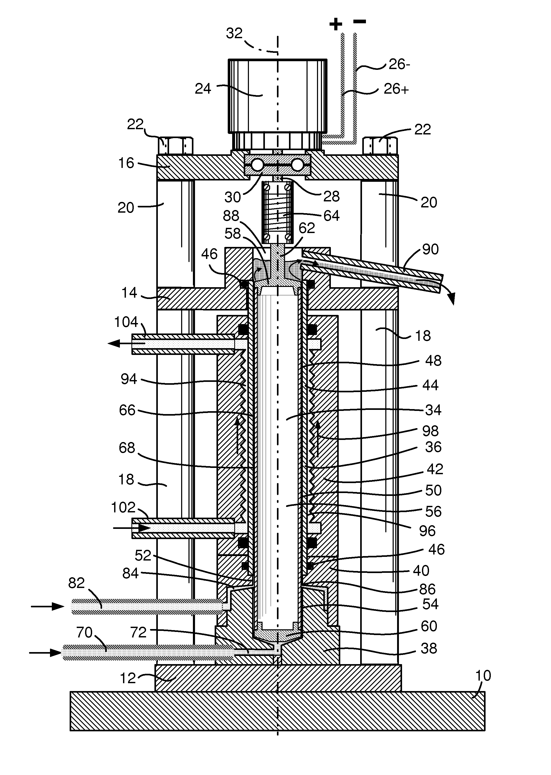
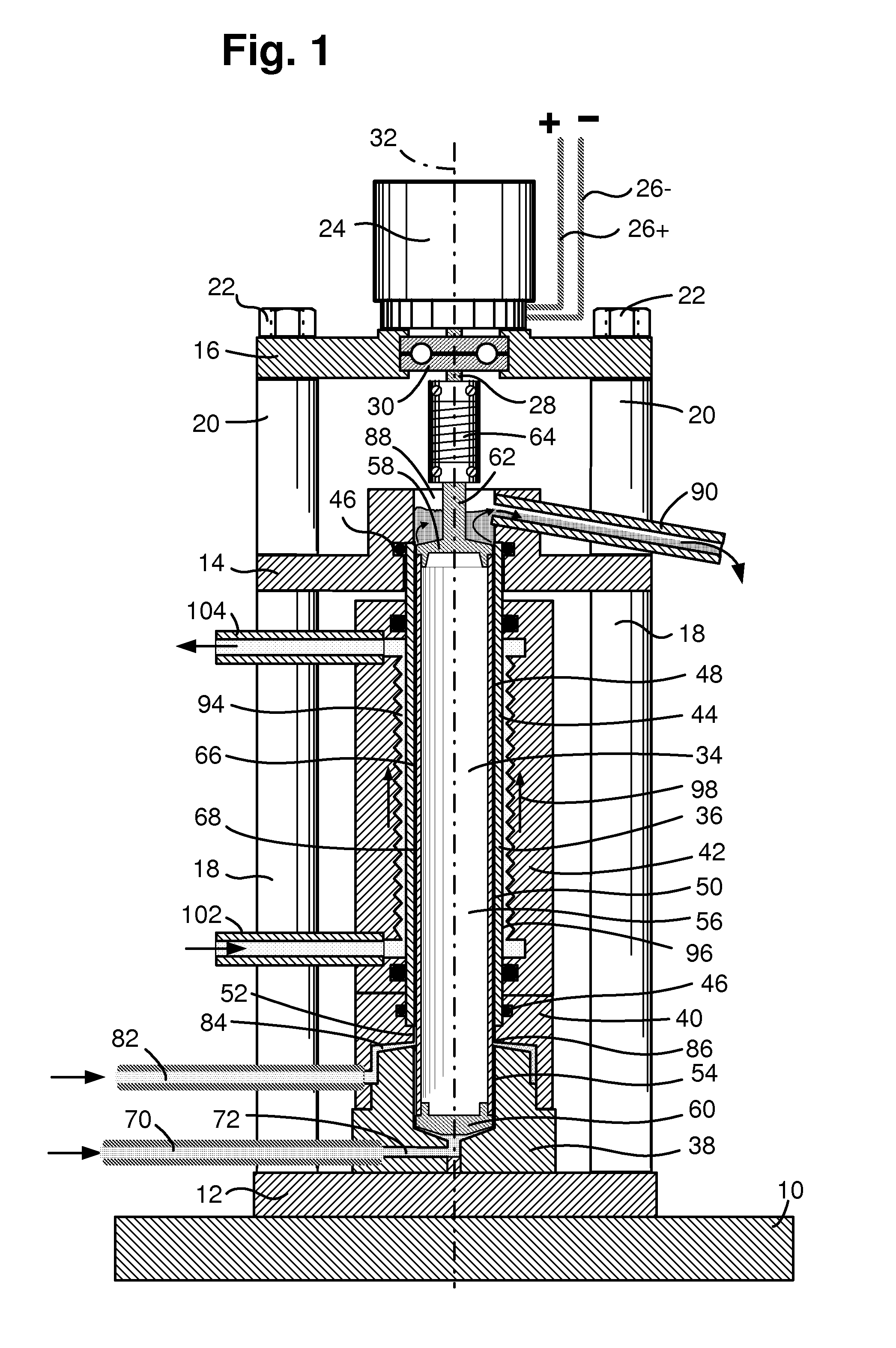
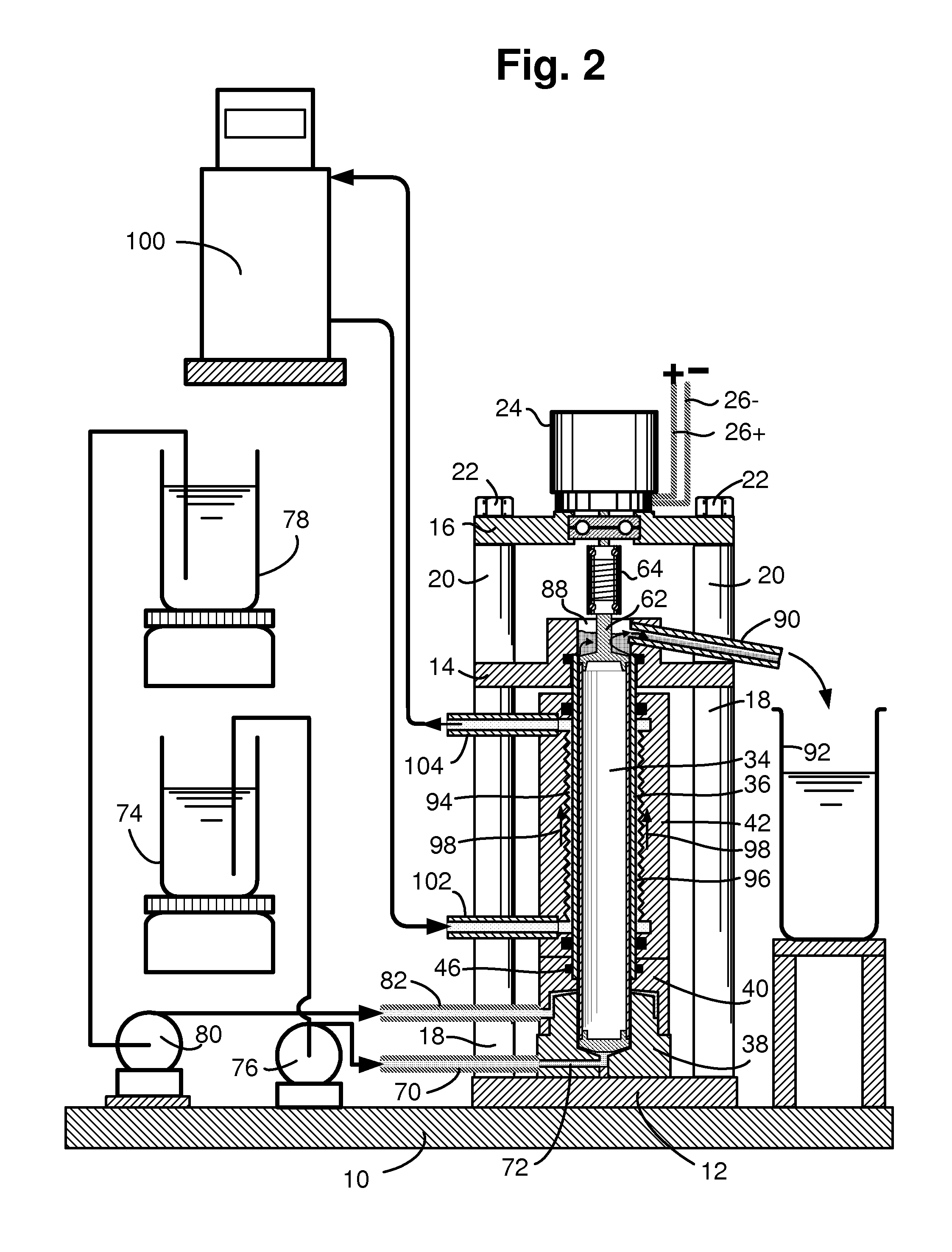
[0027]The main frame of the apparatus comprises a flat main base member 10 on which is disposed a flat sub-base plate 12, a spaced parallel intermediate and stator support plate 14 and a spaced parallel uppermost and motor support plate 16. The members 12 and 14 are held spaced apart by interposed tubular members 18 (only two are shown), and the members 14 and 16 are held spaced apart by interposed tubular members 20 (again only two are shown), the whole assembly being held in tight engagement by tie-rods 22, each of which passes through a respective pair of tubular members 18 and 20. A controllable speed electric drive motor 24, which receives its operating electric power through leads 26+ and 26−, is mounted on the support plate 16 with its drive shaft 28 extending vertically downward through a bearing 30, the length of the drive shaft being sufficient for it to extend below the support plate 16. The axis of rotation of the motor and its shaft is vertical and is indicated by the b...


PUM


Abstract

The heat exchange apparatus provides a flow passage for the heat exchange fluid comprising a succession of flow passage chamber portions separated from one another by intervening throttle forming passage portions of smaller cross section, and therefore of smaller flow capacity, transverse to the flow direction, so that the heat exchange fluid moves at a higher velocity in the throttle forming portions than in the chamber portions. The fluid is moved at a rate such that its velocity in the throttle forming portions is high enough to reduce the thickness of the fluid boundary layer on the passage wall and thereby facilitate the heat exchange. Alternatively, or in addition, the velocity is high enough to at least reduce the rate of fouling of the passage wall surface. Alternatively, or in addition, the fluid flows as eddy vortices, the spacing of the chamber portions along the passage being such that wake interference flow is established which enhances the rate of heat exchange. The exchanger is intended principally for use in combination with a spinning tube in tube reactor with a very small annular cross section reaction passage between them, the exchanger also being of tubular form with the stator tube constituting a wall of the heat exchanger.

Description

FIELD OF THE INVENTION[0001]The invention is concerned with new heat exchange apparatus and especially, but not exclusively, to heat exchange apparatus for use in combination with flow-through chemical reactors of the type usually known as micro-reactors.BACKGROUND OF THE INVENTION[0002]It is fundamental in the chemical industry that the temperature at which a particular reaction is carried out may be critical for successful optimum operation, and therefore it must be maintained within a specific range, which can be very narrow. Variations in the temperature outside this range can, for example, cause unwanted side reactions to occur, reducing the output of the wanted side product, and often requiring expensive further processing to remove the unwanted product or products. Chemical reactions are almost invariably either exothermic or endothermic, and reactions that do not involve heat generation or absorption are rare, so that it is usually essential to provide in combination with th...

Claims


Application Information

Patent Timeline
Patent Type & Authority Applications(United States)
IPC IPC(8): F28F1/00
CPCB01F7/008B01F15/065B01J19/247B01J2219/00094B01J2219/00189F28F19/00B01J2219/00247F28D11/04F28D2021/0022F28F13/02B01J2219/00243B01F27/272B01F35/92
Inventor HOLL, RICHARD A.
Owner HOLL RICHARD A
Why Eureka
Try Eureka