Connection assembly for through tubing conveyed submersible pumps

a submersible pump and connection assembly technology, which is applied in the direction of fluid removal, earth-moving drilling, borehole/well accessories, etc., can solve the problems of limiting the size and length of the esps, and achieve the effect of cross-sectional area

Active Publication Date: 2012-06-21
BAKER HUGHES INC
View PDF3 Cites 8 Cited by
  • Summary
  • Abstract
  • Description
  • Claims
  • Application Information

AI Technical Summary

Benefits of technology

[0007]Disclosed is an embodiment of a method of engaging sections of a pumping system. In one example embodiment the method includes providing a lower section of the pumping system, where the lower section has a connector with a bore on an upper surface that of the connector. The bore has a cross sectional area that decreases with distance away from its opening. The method further includes anchoring the lower section within production tubing disposed in a subterranean well and providing an upper section of the pumping system. The upper section includes a connector with a downward facing pin. The upper section is oriented into a designated azimuth for coupling engagement with the lower section. Orientation takes place by lowering the upper section onto the lower section and inserting the pin into the opening of the bore. The pin follows a generally circular path as it slides to a lowermost portion of the bore that positions the upper section at a designated azimuth for coupling the upper and lower sections. The upper section is engaged to the lower section when the upper section is oriented as desired. In one example, the lower section includes a lower pumping system with a splined drive shaft and the upper section has a driven shaft with splines. In an example embodiment, an annular coupling on the driven shaft has grooves formed on an inner surface and when the upper section is at the designated azimuth, the splines on the drive shaft are aligned with the grooves in the coupling so that the drive shaft can be inserted into a lower end of the coupling. Optionally, fluid can be vented from inside of the coupling when the drive shaft inserts into the coupling. In another alternative embodiment, fluid is pumped from the wellbore by rotating the drive shaft to rotate the driven shaft via the coupling to pressurize the fluid in the lower section and the upper section. An upward force can optionally be applied onto the upper section to disengage the upper section from the lower section. Alternatively, additional sections can be stacked onto the upper section.
[0008]Also disclosed is an embodiment of an electrical submersible pumping (ESP) system. In one example, the ESP system is made up of a lower tandem selectively anchored inside of production tubing that is disposed in a wellbore. A drive shaft is included in the lower tandem that has an end that projects past the lower tandem and splines on its outer surface. In this example, a connector is provided on an upper end of the lower tandem has an upward facing bore with an cross sectional area that decreases with distance away from an opening of the bore. An upper tandem is set on the upper end of the lower tandem that has a driven shaft inserted into an annular coupling. A connector is provided on a lower end of the upper tandem that has a strategically located pin that points downward. In this example, when the upper tandem lands on the lower tandem and the pin is inserted into the opening of the bore, the pin slides along a side of the bore to a designated azimuth and aligns the grooves in the coupling with splines on the drive shaft as the coupling slides over the drive shaft. In one alternative, the splines on the drive shaft have an upper end with a pointed tip. A vent is optionally formed through a sidewall of the coupling. In one alternate embodiment, the connectors are threadingly mounted on the respective upper and lower ends of the lower and upper tandems, and the pin and bore are adjacent respective outer edges of the connectors on the upper and lower tandems. One alternate embodiment includes a plurality of upward facing bores on the connector on the lower tandem and arranged proximate one another. Optionally, a plurality of downward facing pins are on the connector on the upper tandem. In this example, when the upper tandem is lowered onto the lower tandem, the pins engage an opening of one of the bores. Alternatively, the bores are disposed proximate an outer surface of the connector on the lower tandem, and the pins are disposed proximate an outer surface of the connector on the upper tandem.
[0009]Also provided herein is a through tubing electrical submersible pumping (ESP) system, that in one example embodiment includes a lower tandem pump in selective anchoring within a string of production tubing disposed in a wellbore. A drive shaft with splines is included with the lower tandem pump. A shaft coupling is also included that has an axial passage and grooves formed axially along a sidewall of the passage. The ESP system also includes an upper tandem pump in fluid communication with the lower tandem pump and coupled to an upper end of the lower tandem pump having a driven shaft with a lower end engagedly inserted into the shaft coupling. Connectors are provided on the respective upper and lower ends of the lower and upper tandem pumps for azimuthally orienting the upper tandem so the grooves in the shaft coupling align with splines on the drive shaft as the upper tandem is lowered on to the lower tandem. In one example embodiment, the means for orienting the upper tandem include a series of bores that are disposed along a substantially circular path on an upper surface of the lower tandem. In this example, the path is proximate an outer periphery of the lower tandem. Optionally, the means for orienting the upper tandem includes downwardly pointing pins provided along a substantially circular path on a lower surface of the upper tandem. In this embodiment the path is proximate an outer periphery of the upper tandem. Thus when lowered into the bores, the pins slide in a circular path along a side of the bores to a lowermost position and in a designated azimuth.

Problems solved by technology

Safety and environmental concerns limit the maximum length of the lubricator, thereby limiting the size and length of ESPs.

Method used


Image

  • Connection assembly for through tubing conveyed submersible pumps
  • Connection assembly for through tubing conveyed submersible pumps
  • Connection assembly for through tubing conveyed submersible pumps

Examples


Embodiment Construction

[0013]The present invention will now be described more fully hereinafter with reference to the accompanying drawings in which embodiments of the invention are shown. This invention may, however, be embodied in many different forms and should not be construed as limited to the illustrated embodiments set forth herein; rather, these embodiments are provided so that this disclosure will be thorough and complete, and will fully convey the scope of the invention to those skilled in the art. Like numbers refer to like elements throughout.

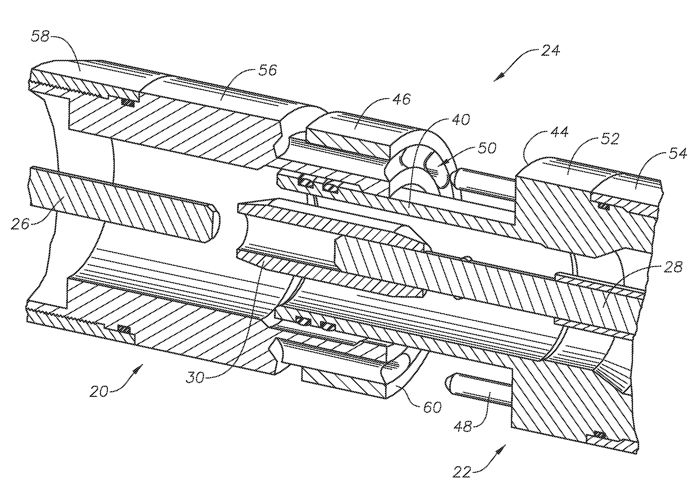
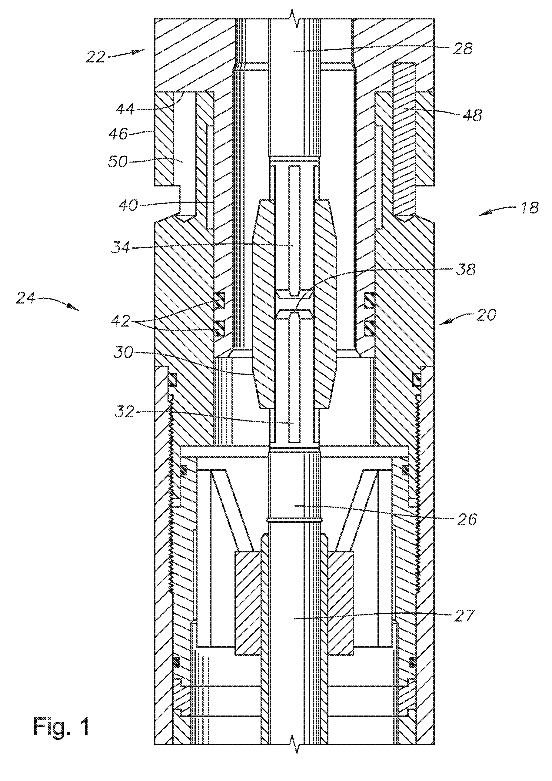
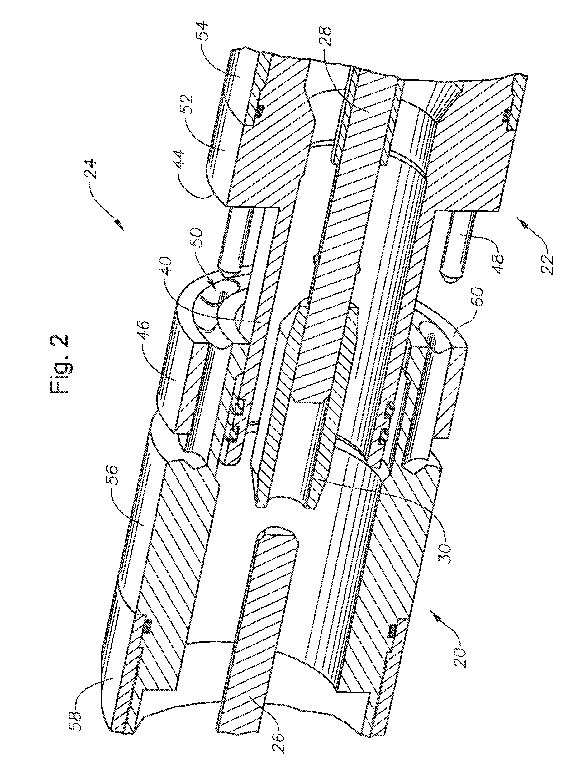
[0014]FIG. 1 is a side sectional view of a connection assembly 18 for connecting a lower tandem 20 to an upper tandem 22, which make up a part of a through tubing conveyed (TTC) pumping system 24. A drive shaft 26 is shown coaxially within the lower tandem 20 and held in place by a bearing assembly 27. The drive shaft 26 is mechanically coupled to a driven shaft 28 shown set coaxial within the upper tandem 22. An annular coupling 30 has a lower end and in...


PUM


Abstract

An electrical submersible pumping (ESP) system for use in a wellbore that can be assembled in the wellbore. Upper and lower pump tandems are fitted with connectors that align the tandems when coupled in the wellbore. The connectors on the lower tandems have bores with enlarged openings on upward facing surfaces. Downward pointing pins are on lower facing surfaces of the connectors on the upper tandems. The cross sectional area of each bore decreases with distance away from the openings, so that as the pins insert into the bores the pins move along a helical path that in turn rotates the upper tandem into a designated azimuth and into alignment with the lower tandem. Properly aligning the upper and lower tandems couples respective drive and driven shafts in the tandems as the upper tandem lands on the lower tandem.

Description

RELATED APPLICATIONS[0001]This application claims priority to and the benefit of co-pending U.S. Provisional Application Ser. No. 61 / 424,937, filed Dec. 20, 2010, the full disclosure of which is hereby incorporated by reference herein.BACKGROUND[0002]1. Field of Invention[0003]This invention relates in general to oil and gas production and in particular to a device for coupling together segments of electrical submersible pumps.[0004]2. Description of Prior Art[0005]An electrical submersible pumping (ESP) system for a hydrocarbon producing well is normally installed within casing on a string of tubing or deployed within the tubing itself. Usually the tubing is made up of sections of pipe screwed together. Coiled tubing deployed from a reel may also be used. The motor is often powered with a power cable that is strapped alongside the tubing. The pump is typically located above the motor, is connected to the lower end of the tubing, and pumps fluid through the tubing to the surface. On...

Claims


Application Information

Patent Timeline
Patent Type & Authority Applications(United States)
IPC IPC(8): E21B43/00
CPCE21B43/128
Inventor TETZLAFF, STEVEN K.ROBINSON, LANCE
Owner BAKER HUGHES INC
Why Eureka
Try Eureka