Check patentability & draft patents in minutes with Patsnap Eureka AI!

Electrostatic atomization device

Inactive Publication Date: 2012-06-21
PANASONIC CORP
View PDF7 Cites 8 Cited by
  • Summary
  • Abstract
  • Description
  • Claims
  • Application Information

AI Technical Summary

Benefits of technology

[0006]It is an object of the present invention to provide an electrostatic atomization device that prevents air discharge and the generation of a large amount of ozone with low cost and without the need for performing feedback control.
[0007]One aspect of the present invention is an electrostatic atomization device provided with a transformer including a primary coil and a secondary coil. A switching element is connected in series to the primary coil of the transformer. A switching element drive circuit provides the switching element with a pulse signal to perform a switching operation with the switching element and generate high voltage from the secondary coil of the transformer. A discharge unit including a discharge electrode performs electrostatic atomization on liquid supplied to the discharge electrode to generate charged fine liquid droplets when the high voltage generated by the secondary coil is applied to the discharge electrode. The switching element drive circuit generates a pulse signal having an oscillation frequency set so that the transformer has drooping characteristics that prevent air discharge from occurring between the discharge electrode and ground and prevent ozone having a predetermined concentration or greater when the liquid undergoes electrostatic atomization even when load on the discharge unit varies.

Problems solved by technology

This results in repetitive occurrence of Rayleigh breakups and causes electrostatic atomization of the water.
Further, when too much water collects on the discharge electrode, excessive current flows to the discharge electrode.

Method used


Image

  • Electrostatic atomization device
  • Electrostatic atomization device
  • Electrostatic atomization device

Examples


Embodiment Construction

[0015]An electrostatic atomization device 1 according to one embodiment of the present invention will now be discussed with reference to the drawings.

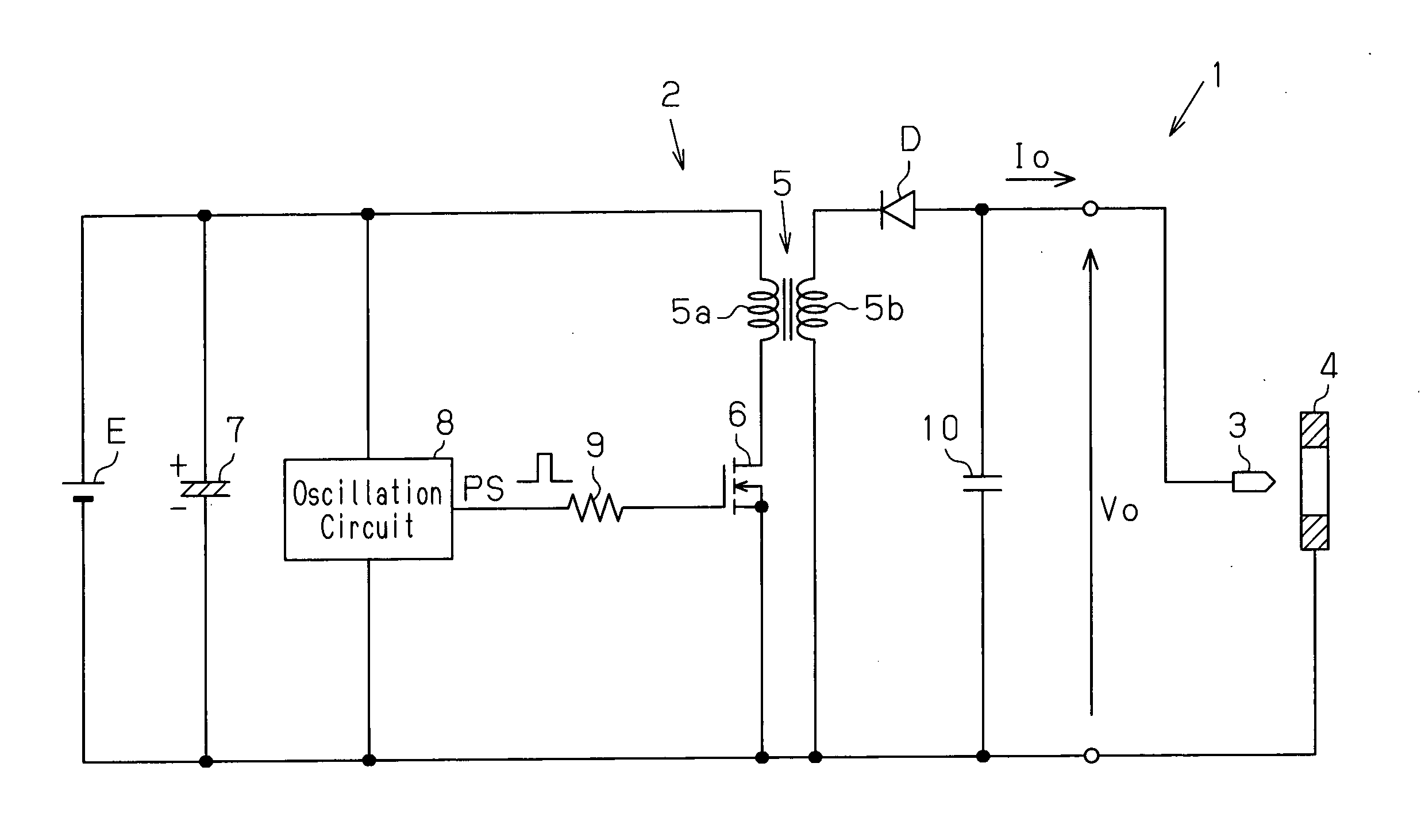
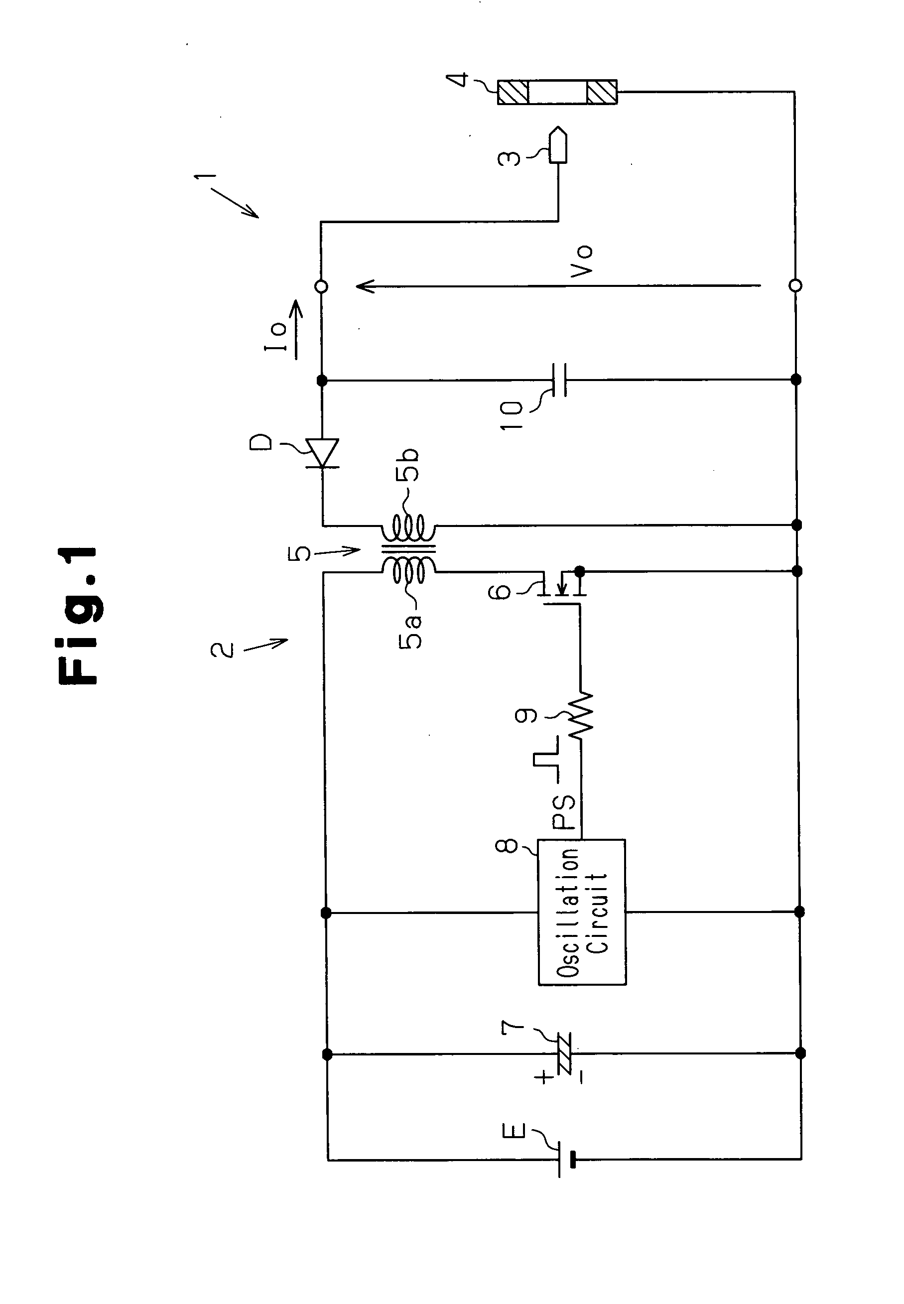
[0016]FIG. 1 shows a high voltage generation circuit 2 of the electrostatic atomization device 1. The high voltage generation circuit 2 applies high voltage between a discharge electrode 3 and ground, namely, a ground electrode 4, which form a discharge unit arranged in the electrostatic atomization device 1. The discharge electrode 3 and the ground electrode 4 are spaced apart from each other by a predetermined distance. In a state in which water, serving as liquid, is supplied to the distal end of the discharge electrode 3, the high voltage generation circuit 2 applies high voltage between the discharge electrode 3 and the ground electrode 4.

[0017]As a result, Coulomb force locally raises the liquid surface of the water supplied to the distal portion of the discharge electrode 3 into a conical form (Taylor cone). The raised conical f...


PUM


Abstract

An electrostatic atomization device provided with a transformer including primary and secondary coils. A switching element is connected in series to the primary coil. A switching element drive circuit provides the switching element with a pulse signal to perform a switching operation and generate high voltage from the secondary coil. A discharge unit including a discharge electrode performs electrostatic atomization on liquid supplied to the discharge electrode to generate charged fine liquid droplets when high voltage generated by the secondary coil is applied to the discharge electrode. The switching element drive circuit generates a pulse signal having an oscillation frequency set so that the transformer has drooping characteristics that prevent air discharge from occurring between the discharge electrode and ground even when load on the discharge unit varies and prevents the generation of ozone having a predetermined concentration or greater when the liquid undergoes electrostatic atomization.

Description

TECHNICAL FIELD[0001]The present invention relates to an electrostatic atomization device.BACKGROUND ART[0002]Japanese Laid-Open Patent Publication Nos. 2006-334503 and 2007-21370 each describe a prior art example of an electrostatic atomization device that generates charged fine water droplets of nanometer size. In a state in which water is supplied to the distal end of a discharge electrode by using capillary action, the electrostatic atomization device applies high voltage to the discharge electrode. When high voltage is applied to the discharge electrode, the water supplied to the discharge electrode is charged. This results in repetitive occurrence of Rayleigh breakups and causes electrostatic atomization of the water. As a result, the electrostatic atomization device generates charged fine water droplets of nanometer size.[0003]In such a type of electrostatic atomization device, a self-oscillating flyback ringing choke converter (RCC) is used as a switching power supply. The s...

Claims


Application Information

Patent Timeline
IPC IPC(8): F23D11/32
CPCB05B5/0255H02M3/3381B05B5/053
Inventor IMAI, BUNGOKITAMURA, HIROYASUYAMASHITA, MIKIHIRO
Owner PANASONIC CORP
Features
  • R&D
  • Intellectual Property
  • Life Sciences
  • Materials
  • Tech Scout
  • Unparalleled Data Quality
  • Higher Quality Content
  • 60% Fewer Hallucinations
Learn More