
Ion Transfer Tube for a Mass Spectrometer System

a mass spectrometer and ion transfer technology, applied in the field of mass spectrometer systems, can solve the problems of limited maximum temperature that can be applied to the ion transfer tube, limited experimentally, and inability to effectively match the round-cross-section bore, so as to achieve the effect of maximizing either the efficiency of transfer

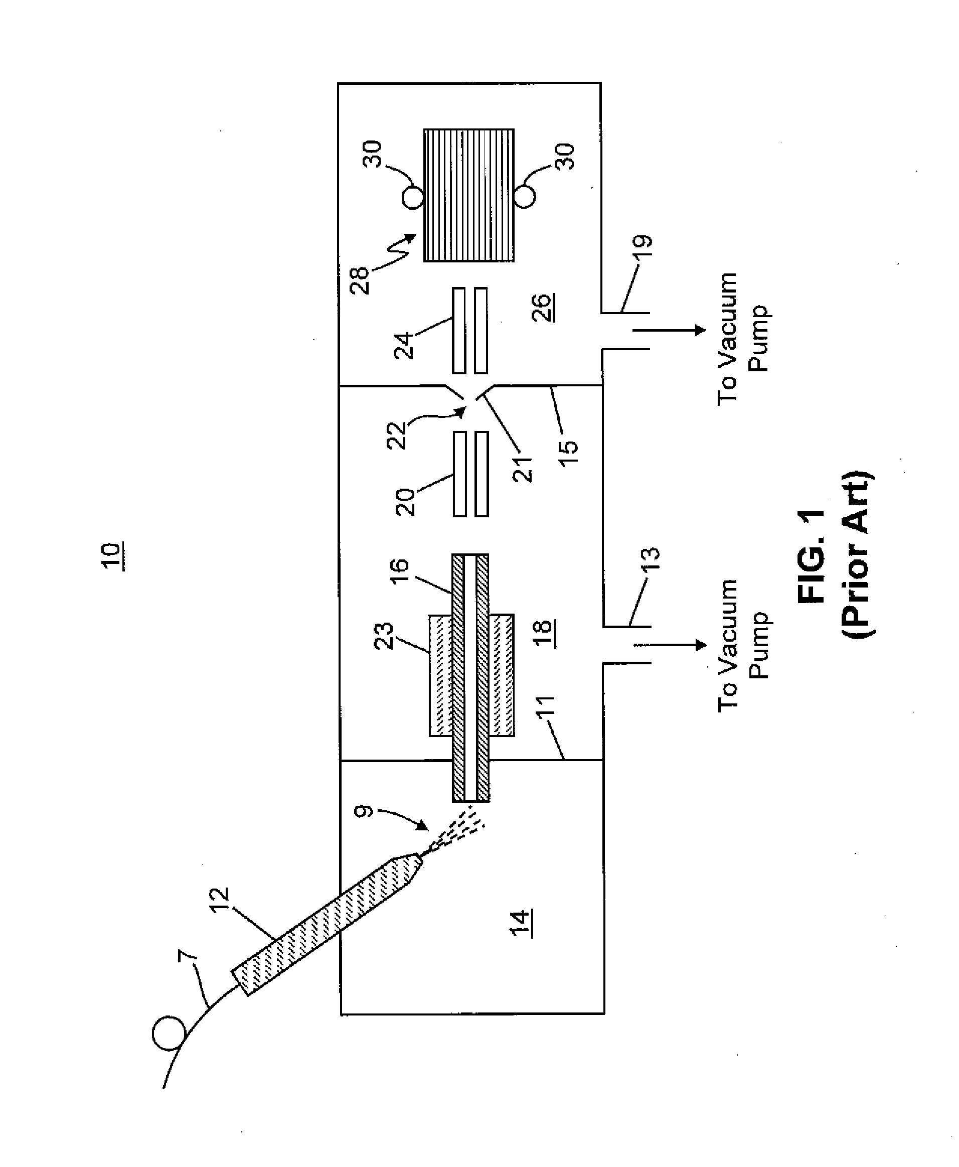
Active Publication Date: 2012-06-21
THERMO FINNIGAN
View PDF2 Cites 27 Cited by
  • Summary
  • Abstract
  • Description
  • Claims
  • Application Information

AI Technical Summary

Benefits of technology

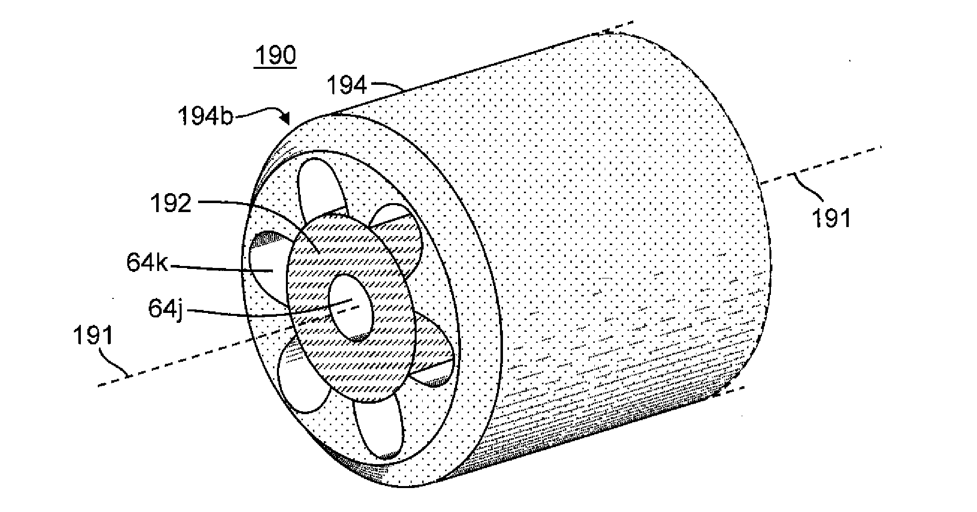
The present patent text describes various improvements to ion transfer tubes used in mass spectrometers. These improvements include the use of non-circular cross-sections for the tubes, such as elliptical, obround, or "letterbox" shapes, with either square or rounded corners. The tubes may also have separate bores or channels with non-contiguous interior bores or channels that have a cross-sectional area that decreases in the direction of flow through the tube. The tubes may also have one or more internal or external features, such as lobes or slots, to improve the efficiency of transfer of ions or heat. The patent also describes systems that use multiple simultaneously emitting individual ion emitters coupled to an ion transfer tube, with the tube having a contiguous interior bore or channel with a cross-sectional shape that maximizes the transfer of charged particles or heat. The methods for forming the ion transfer tube include steps of providing a tube member with an internal bore and a length, and using a laser or other means to create the non-circular cross-sections in the tubes. These improvements and methods help to improve the performance and reliability of ion transfer tubes in mass spectrometers.

Problems solved by technology

However, this approach of increasing the throughput of the ion transfer tube, either by shortening it or increasing its inner diameter, has been found experimentally to be limited by how well the solvent surrounding the ions can be evaporated during the transfer time of the tube.
Unfortunately, the maximum temperature that can be applied to the ion transfer tube is limited due to melting of nearby plastic parts as well as to fragmentation of fragile molecular ions such as certain peptides that may flow through the tube.
Another disadvantage arising from use of the conventional ion transfer tube is the inability of the round-cross-section bore to effectively match—and thus efficiently capture ions from—the charged particle plumes produced by linear or otherwise configured arrays of simultaneously emitting ion sources, i.e. discrete or as part of a monolithically formed microchip assembly.
However, such ion transfer tube arrays are more costly to implement than is a single ion transfer tube and are difficult to align, couple to an ion source and extract and replace for cleaning.

Method used


Image

  • Ion Transfer Tube for a Mass Spectrometer System
  • Ion Transfer Tube for a Mass Spectrometer System
  • Ion Transfer Tube for a Mass Spectrometer System

Examples


Embodiment Construction

[0053]The following description is presented to enable any person skilled in the art to make and use the invention, and is provided in the context of a particular application and its requirements. Various modifications to the described embodiments will be readily apparent to those skilled in the art and the generic principles herein may be applied to other embodiments. Thus, the present invention is not intended to be limited to the embodiments and examples shown but is to be accorded the widest possible scope in accordance with the features and principles shown and described.

[0054]To more particularly describe the features of the present invention, please refer to FIGS. 3 through 22 in conjunction with the discussion below.

[0055]FIG. 3 is a cross sectional view of a portion of an ion transfer tube, ion transfer tube 100, in accordance with various embodiments of the instant teachings. The internal bore of the ion transfer tube 100 comprises a slot 64a in the tube material 102 that ...


PUM

PropertyMeasurementUnit
pressureaaaaaaaaaa
diameteraaaaaaaaaa
heightaaaaaaaaaa

Abstract

An ion transfer tube for a mass spectrometer comprises a core member and a first jacket tube member at least partially enclosing the core member and providing one or more channels therethrough. A method of forming an ion transfer tube, comprises: providing a first jacket tube member having a length and an internal bore, the internal bore passing along the length and defining an interior surface of circular cross section; removing at least one portion of the first jacket tube member adjacent to the interior surface so as to form at least one groove, channel, slot, recess or embayment of or in the interior surface; and providing a core member within the bore of the jacket tube member such that remnant portions of the interior surface of circular cross section mate against portions of an exterior surface of the core member.

Description

CROSS REFERENCE TO RELATED APPLICATION[0001]This application is a Continuation-in-Part of and claims, under 35 U.S.C. 120, the benefit of the filing date of co-pending U.S. patent application Ser. No. 12 / 858,726 filed on Aug. 18, 2010 and titled “Ion Transfer Tube Having Single or Multiple Elongate Bore Segments and Mass Spectrometer System” and assigned to the assignee of the instant application.FIELD OF THE INVENTION[0002]This invention generally relates to mass spectrometer systems, and more specifically to an ion transfer tube for transporting ions between regions of different pressure in a mass spectrometer.BACKGROUND OF THE INVENTION[0003]Ion transfer tubes are well-known in the mass spectrometry art for transporting ions from an ionization chamber, which typically operates at or near atmospheric pressure, to a region of reduced pressure. Generally described, an ion transfer tube typically consists of a narrow elongated conduit having an inlet end open to the ionization chambe...

Claims


Application Information

Patent Timeline
Patent Type & Authority Applications(United States)
IPC IPC(8): H01J49/04B23P11/00H01J49/26
CPCY10T29/49826B23H9/14B23H7/02H01J49/0404
Inventor WOUTERS, ELOY R.MAKAROV, ALEXANDER A.ATHERTON, R. PAULDUNYACH, JEAN JACQUES
Owner THERMO FINNIGAN
Learn More