Device for pre-tensioning a machine frame, machine frame, and pressing and drawing device

a technology for pretensioning and machine frames, which is applied in the direction of presses, manufacturing tools, forging presses, etc., can solve the problems of difficult installation of such machine frames, large weight large dimensions of such steel columns, so as to achieve easy installation and maintenance, and the effect of reducing the number of components

Inactive Publication Date: 2012-06-21
SMS MEER
View PDF4 Cites 7 Cited by
  • Summary
  • Abstract
  • Description
  • Claims
  • Application Information

AI Technical Summary

Benefits of technology

[0014]It is the task of the present invention to further develop pre-tensioning devices of the type stated, in such a manner that they

Problems solved by technology

The design, which is heavy in terms of weight, and particularly makes installation of such machine frames difficult, is also a disadvantage.
Furthermore, the dimensions, particularly the length, of such a steel column are also an impediment, since pressing devices, in particular, are often presses having a height of several meters.
However, the sheet-metal lamellae are still very high in terms of construction, when a press having a height of several

Method used


Image

  • Device for pre-tensioning a machine frame, machine frame, and pressing and drawing device
  • Device for pre-tensioning a machine frame, machine frame, and pressing and drawing device
  • Device for pre-tensioning a machine frame, machine frame, and pressing and drawing device

Examples


Embodiment Construction

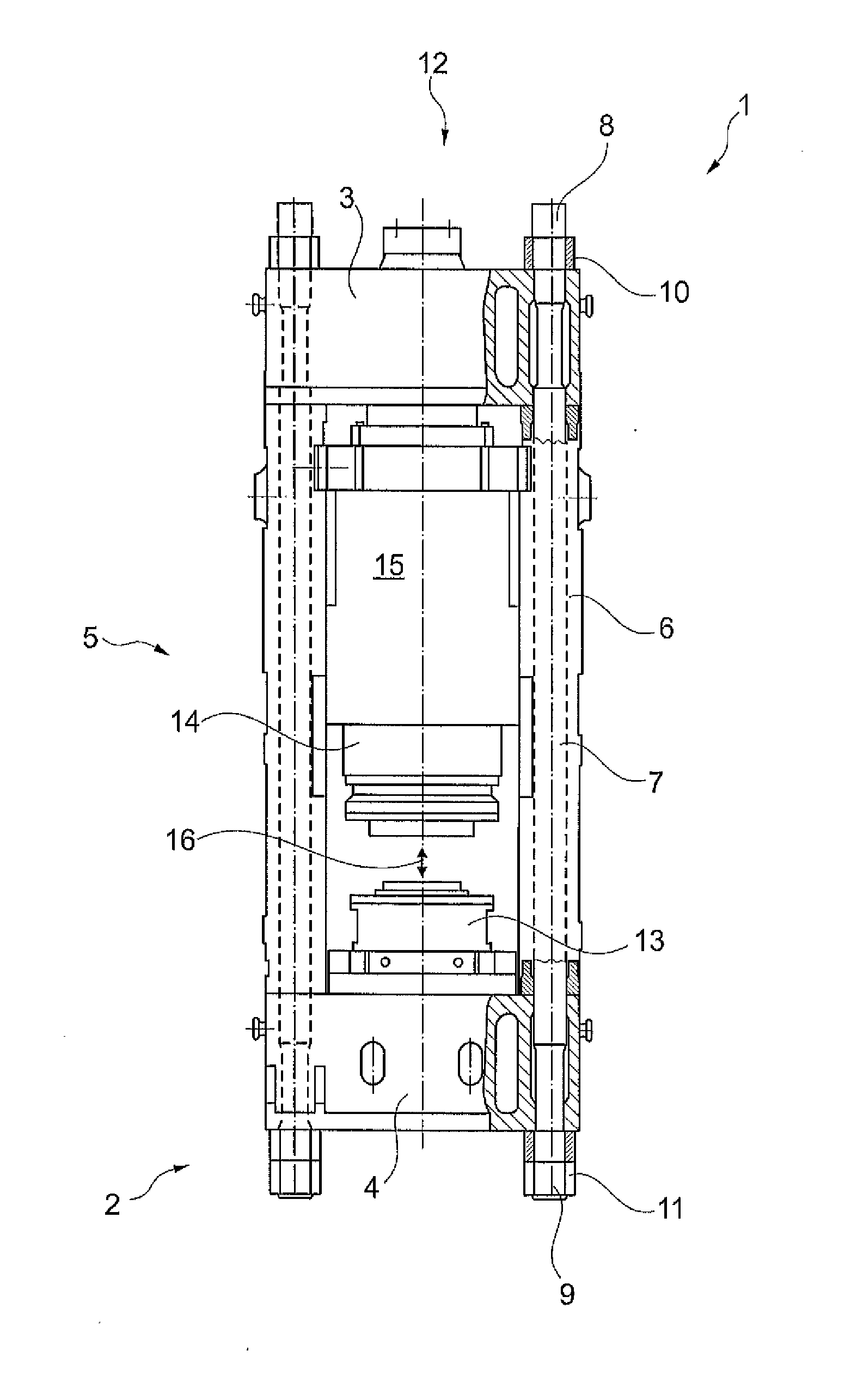
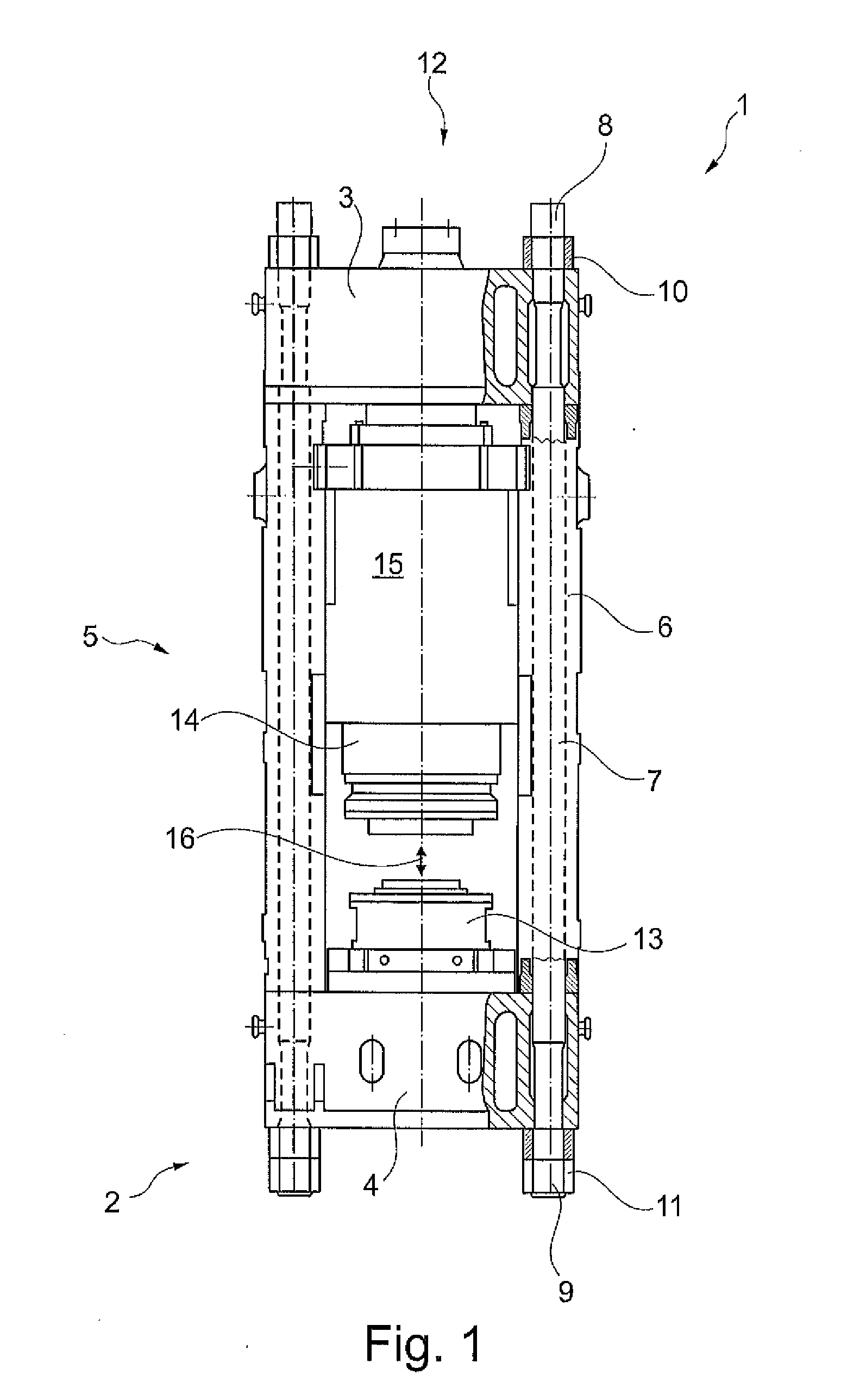
[0071]The press 1 shown in FIG. 1 has a typical structure, known from the state of the art, of a press frame 2, which essentially comprises a cylinder crossbar 3 and a counter-crossbar 4, as well as a stand mechanism 5 composed of four individual pressure supports 6 (numbered only as an example here). A tension rod 7 composed of steel is disposed within each of the pressure supports 6. Each of the tension rods 7 projects beyond the cylinder crossbar 3 and also beyond the counter-crossbar 4 on the outside, so that a tensioning nut 10 or 11 (numbered only as examples here) can be screwed onto the ends 8 and 9, in each instance, of the tension rods 7, in each instance. While the pressure supports 6 space the cylinder crossbar 3 and the counter-crossbar 4 apart from one another, the press frame 2 as a whole is pre-tensioned by means of the tension rods 7. This is done in that the two tensioning nuts 10 and 11 of the tension rod 7, in each instance, are tightened, so that the components ...


PUM

PropertyMeasurementUnit
Lengthaaaaaaaaaa
Forceaaaaaaaaaa
Shapeaaaaaaaaaa

Abstract

A device for pre-tensioning a machine frame has a tie rod including a first and a further rod head for placement on the machine frame and a tension element for absorbing tensile forces between the rod heads. The tension element extends along a tension distance of the tie rod. At least one of the two rod heads includes a device for reversing the direction for the tension element. In further aspects, a machine frame and a pressing or drawing device are provided.

Description

CROSS REFERENCE TO RELATED APPLICATIONS[0001]This application claims priority under 35 U.S.C. §119(e) and the benefit of U.S. Provisional Application No. 61 / 460,335 filed Dec. 30, 2010 and under 35 U.S.C. §119 of German Application No. 10 2010 055 339.5 filed Dec. 21, 2010, the disclosures of which are incorporated by reference.BACKGROUND OF THE INVENTION[0002]1. Field of the Invention[0003]The invention relates to a device for pre-tensioning a machine frame, having a tie rod comprising a first and a further rod head for placement on the machine frame and comprising a tension element for absorbing tensile forces between the rod heads, whereby the tension element extends along a tension distance of the tie rod.[0004]The invention also relates to a machine frame having an upper crosshead and a lower crosshead for absorbing processing forces introduced into the machine frame, having frame elements for spacing the crossheads apart from one another, and having at least one tie rod that a...

Claims


Application Information

Patent Timeline
IPC IPC(8): B21F9/00
CPCB30B15/042B30B15/04B21J13/04B21J9/00
Inventor SCZESNY, WERNERSIEMER, EKHARD
Owner SMS MEER
Why Eureka
Try Eureka