Electrical energy generation device

a technology of energy generation device and energy recovery, which is applied in the direction of electrostatic generator/motor, capacitor with temperature varied dielectric, capacitor, etc., can solve the problems of low efficiency of systems, incompatibility with use, and difficult optimization of systems

Inactive Publication Date: 2012-06-21
STMICROELECTRONICS (CROLLES 2) SAS
View PDF4 Cites 5 Cited by
  • Summary
  • Abstract
  • Description
  • Claims
  • Application Information

AI Technical Summary

Benefits of technology

[0028]In other words, advantage can be taken of the fact that, in the operating cycle thereof, the temperature of the ferr...

Problems solved by technology

Such systems seem difficult to optimize and are apparently not really compatible with use in the microelectronic field, where scale factors impose sizing constraints.
Such systems generally have low efficiency and are the source of wear, due to the fact that the energy recovery is related to the movement of rotary parts, and are especiall...

Method used


Image

  • Electrical energy generation device
  • Electrical energy generation device
  • Electrical energy generation device

Examples


Embodiment Construction

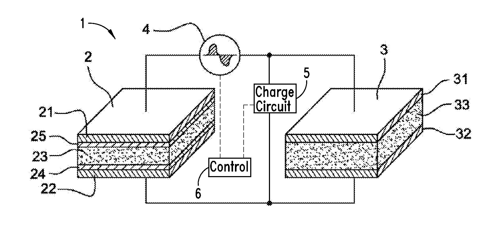
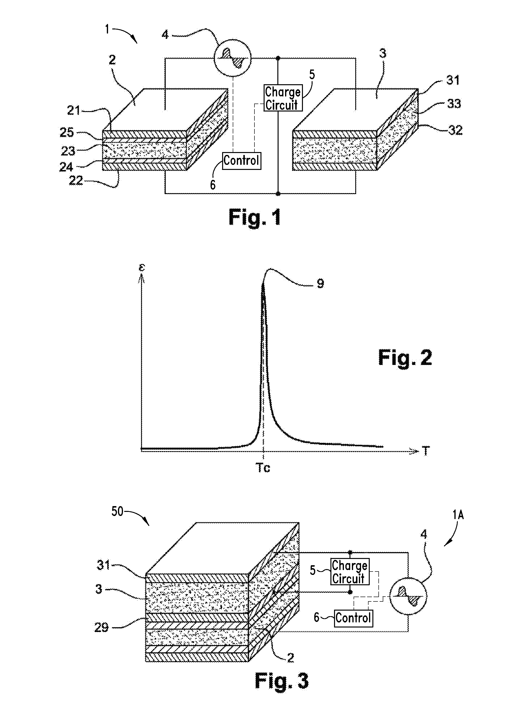
[0039]As illustrated in FIG. 1, an electrical energy generation device 1 comprises a capacitor 2, a capacitive element 3 and a recovery circuit 4, interposed between an electrode 21 of the capacitor 2 and an electrode 31 of the capacitive element 3.

[0040]More precisely, the capacitor 2 has two electrodes 21, 22 facing each other. Between these electrodes 21, 22, a layer 23 made from a ferroelectric material is present. This ferroelectric material may for example be barium titanate (BaTiO3) or lead titanate (PbTiO3), or more generally other ferroelectric oxides with a perovskite structure.

[0041]In the form illustrated in FIG. 1, the ferroelectric material present in the capacitor 2 is isolated from the electrodes 21, 22 by dielectric layers 24, 25. Such an arrangement prevents contact between the ferroelectric material 23 and the metal of the electrodes 21, 22, which may be advantageous vis-à-vis the manufacturing method.

[0042]However, these isolation layers may not be necessary acco...


PUM


Abstract

A device for generating electrical energy from the heat dissipated by a heat source, comprising: a capacitor comprising two electrodes between which a ferroelectric material is present, said capacitor being arranged so as to be positioned to capture all or part of the heat dissipated by said heat source; a capacitive element a first electrode of which is connected to a first electrode of said capacitor; a recovery circuit interposed between the second electrode of said capacitor and the second electrode of the capacitive element, and able to have the current flowing between said second electrodes pass through it. a mechanism adapted to move the capacitor with respect to the heat source, said mechanism having at least one arm able to move between two positions, the capacitor being closer to the heat source in one of the two positions.

Description

BACKGROUND[0001]1. Technical Field[0002]The present disclosure concerns an energy recovery device enabling energy available in the form of heat to be converted into electrical energy.[0003]It finds a particular but not exclusive application in the field of electronics, enabling energy dissipated by components or electronic circuits to be recovered. In the remainder of the description, it will be described in a more detailed manner for this application, but it can also be associated with various other heat sources (such as for example boilers, industrial equipment, motors, etc.) and can be combined in general terms with any energy recovery device, for example solar, vibratory or thermal energy recovery devices.[0004]2. Description of the Related Art[0005]In general terms, electronic systems, in particular electronic components, give rise to electric currents that by Joule effect cause dissipation of energy in the form of heat.[0006]This dissipation of energy reduces the efficiency of...

Claims


Application Information

Patent Timeline
IPC IPC(8): H02N1/00
CPCH01L37/02H01G9/155H01G9/0003H01G2/08H01G7/04H10N15/10
Inventor SKOTNICKI, THOMASMONFRAY, STEPHANE
Owner STMICROELECTRONICS (CROLLES 2) SAS
Why Eureka
Try Eureka