Current detector

a current detector and detector technology, applied in the field of current detectors, can solve the problems of insufficient safety, insufficient detection of battery over-charge or over-discharge, and substantial deterioration of battery, and achieve accurate detection, small heat capacity, and correct variation of electric resistance of shunt resistors

Inactive Publication Date: 2019-11-28
SANYO ELECTRIC CO LTD
View PDF0 Cites 4 Cited by
  • Summary
  • Abstract
  • Description
  • Claims
  • Application Information

AI Technical Summary

Benefits of technology

[0007]A current detector according to an aspect of the present invention includes a shunt resistor, and a temperature sensor that detects a temperature that corrects variation in electric resistance of the shunt resistor caused by a temperature of the shunt resistor. The temperature sensor includes a pair of temperature detecting leads that form a thermocouple. A measurement point at front ends of the pair of temperature detecting leads is electrically and thermally connected to the shunt resistor, and is fixed to the shunt resistor.
[0008]The current detector described above very accuracy detects electric current by means of the shunt resistor. Electric current that sharply varies is especially promptly and very accurately detected by the current detector described above. The reason is that the current detector described above detects a temperature of the shunt resistor by means of the thermocouple that has a small heat capacity. The shunt resistor is a resistor that detects electric current. Another reason is that an insulation sheet is not between the measurement point of the thermocouple and the shunt resistor, and thus the measurement point of the thermocouple is electrically connected to and thermally coupled to the shunt resistor. The thermocouple includes the pair of temperature detecting leads made of different types of metals, respectively. The pair of temperature detecting leads are electrically connected to each other at the measurement point at front ends of the pair of temperature detecting leads. Since the measurement point is made of metal, the measurement point is surely and electrically connected to a surface of the shunt resistor made of metal, using methods, such as welding. Since the thermocouple is electrically and directly connected to a surface of the shunt resistor, thermal resistance and a heat capacity between the measurement point and the shunt resistor are very small. Therefore, the thermocouple promptly transfers a temperature of the shunt resistor to the measurement point. Therefore, the thermocouple very accurately detects temperatures of the shunt resistor that vary.
[0009]FIG. 3 illustrates temperatures of the shunt resistor that vary due to electric current that flows through the shunt resistor. In FIG. 3, curve A represents variation in electric current, curve B represents characteristic detection of temperatures by a temperature detector according to an aspect of the present invention, and curve C represents temperatures detected by a thermistor disposed at the shunt resistor. Then, an insulation sheet is between the thermistor and the shunt resistor. As illustrated in FIG. 3, while temperatures of the shunt resistor sharply vary because electric current significantly varies, the temperature detector according to an aspect of the present invention promptly and accurately detects the varying temperatures w...

Problems solved by technology

If the remaining capacity is not accurately detected, the fact that the battery is over-charged or over-discharge...

Method used


Image

  • Current detector
  • Current detector
  • Current detector

Examples


Embodiment Construction

[0019]Hereinafter, an exemplary embodiment of the present invention will be described with reference to the drawings. However, the exemplary embodiment described later exemplifies a current detector that embodies a technical idea of the present invention. The present invention is not limited to the current detector described later.

[0020]In the present description, to facilitate understanding the claims, reference marks that correspond to components described in the exemplary embodiment are assigned to components recited in “Claims” and “Solutions to problem and advantageous effects of invention”. However, the components recited in the claims are not limited to the components described in the exemplary embodiment.

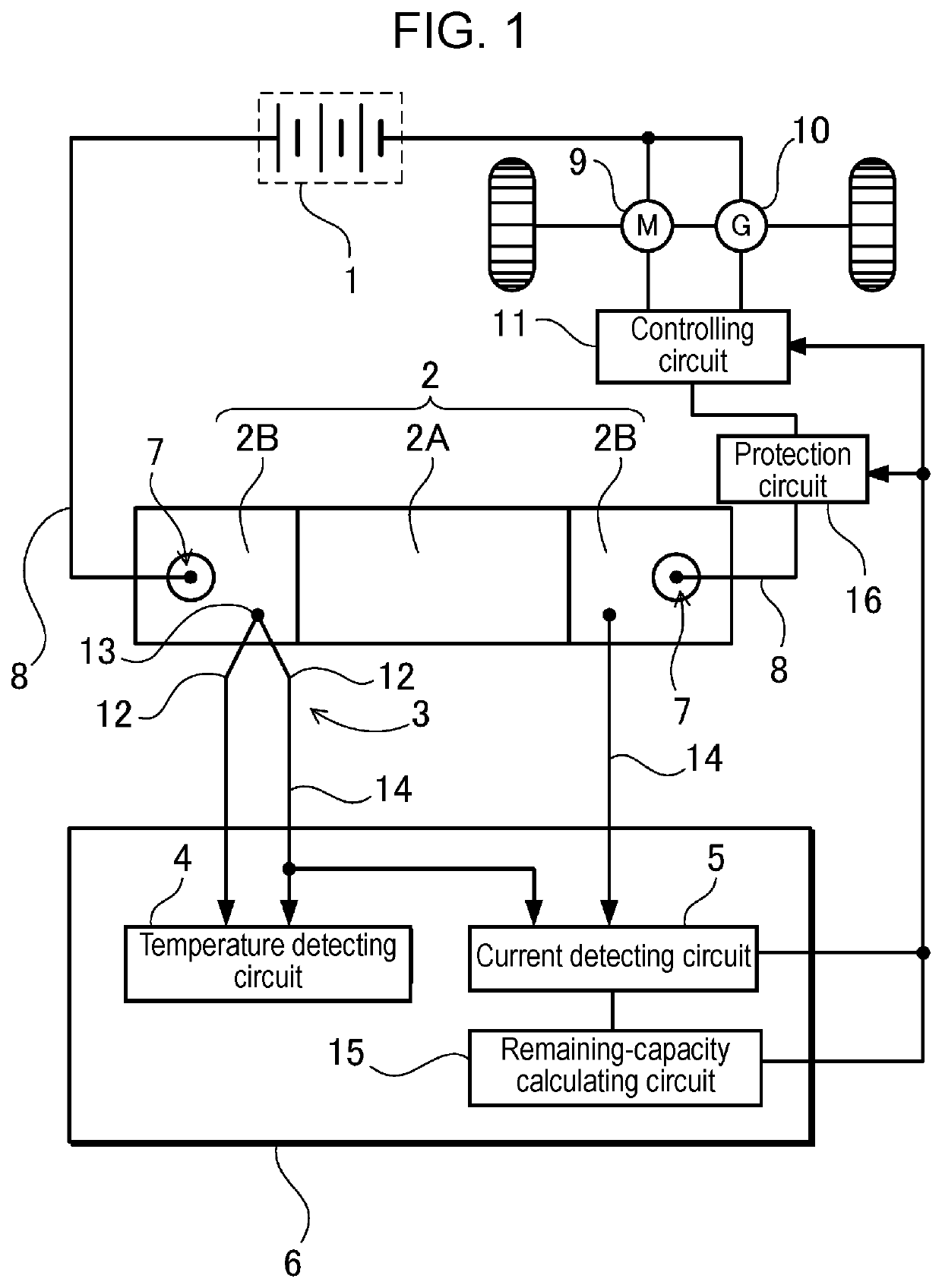
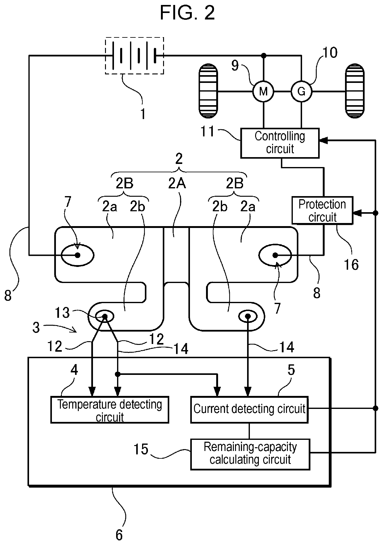
[0021]FIGS. 1 and 2 each illustrate a current detector attached to a vehicle. The current detector detects electric current that charges or discharges battery 1 for traveling. The current detector includes shunt resistor 2 connected to battery 1 in series, temperature sensor...


PUM


Abstract

A current detector includes a temperature sensor that detects a temperature that corrects variation in electric resistance of a shunt resistor caused by a temperature of the shunt resistor. The shunt resistor detects electric current. The temperature sensor includes a thermocouple. The thermocouple includes a pair of temperature detecting leads made of different types of metals, respectively. The pair of temperature detecting leads are connected to each other at a measurement point at front ends of the pair of temperature detecting leads. A measurement point of the thermocouple is electrically connected to the shunt resistor.

Description

TECHNICAL FIELD[0001]The present invention mainly relates to a current detector that detects large electric current, and relates particularly to a current detector that is most suitable to detect electric current that charges or discharges a battery for traveling that supplies electric power to a motor for traveling of a vehicle.BACKGROUND ART[0002]A battery is used as a power source that is attached to a hybrid vehicle or an electric vehicle and supplies electric power to a motor for traveling. It is particularly important to accurately detect electric current, and accurately calculate a remaining capacity of the battery, based on values of detected electric current. The reason is that the battery is protected by controlling electric current that charges or discharges the battery, and thus maintaining the remaining capacity of the battery within a predetermined range. If the remaining capacity is not accurately detected, the fact that the battery is over-charged or over-discharged ...

Claims


Application Information

Patent Timeline
IPC IPC(8): G01R19/32G01R31/3842
CPCG01R15/146G01R19/32H01M2220/20H01M10/48Y02E60/10G01R31/3842
Inventor NAKANO, SHINYAKUNIMITSU, TOMONORIKOYAMA, KATSUTOSHI
Owner SANYO ELECTRIC CO LTD
Why Eureka
Try Eureka