Electronic current transformer based on complete self-excitation power supply

a technology of electrical current transformer and complete self-excitation, which is applied in the direction of power conversion system, inductance, and conversion with intermediate conversion to dc, etc., can solve the problems of difficult on-site operation and maintenance, insufficient wake-up time of the transformer, and high cos

Inactive Publication Date: 2012-06-21
XIAN HWELL OPTIC ELECTRIC TECH
View PDF9 Cites 6 Cited by
  • Summary
  • Abstract
  • Description
  • Claims
  • Application Information

AI Technical Summary

Benefits of technology

[0006]The electronic current transformer (ECT) based on complete self-excitation power supply provided by the present invention uses two branch circuits to obtain energy directly and respectively from the magnetic field of the bus bar which is to be measured, synthesizes the two output waveforms to fill the wave trough of each other, so as to reduce the pulse of direct current. In this way, the value of the trough voltage of the synthesized wave is higher than the required stabilizing value of direct voltage and it directly meets the input requirement of the stabilizing module of the voltage-stabilizing circuit. The nonlinear filtering and energy storing circuit overcomes the shortcoming of slow voltage rise in the general linear filter. As a result, it is possible to activate the A / D converting circuit rapidly. The present invention has solved the problem of delay caused by using a single coil to obtain energy and using general linear filtering, and has characteristics of small wake-up current, rapid activation and wide application. It is possible to omit additional laser power supply device, simplify the architecture of the active electronic current transformer, improve the reliability of operation and service life, and reduce the cost.

Problems solved by technology

The key for implementing such technology development is that, there are optical fiber communications between the high voltage side and low voltage side, and a power supply for a digital circuit is required to be set at the high voltage side, so as to digitize the magnitude of current; this is the biggest technical problem confronted during the manufacturing of the electronic transformer.
The disadvantages for such method include: {circle around (1)} the life period of the laser source is short with about only 8000-10000 hours; {circle around (2)} the cost is expensive at about 12,000¥, which is more than half of the cost of a whole 110 kv transformer; {circle around (3)} the environmental condition required by the laser is strict, as a result, it is difficult to conduct the on-site operation and maintenance.
At that time, the wake-up current is reduced to less than 800 mA with the use of the technical measure, but the problem of wake-up time for the transformer has not resolved completely yet.
To overcome this shortcoming and reduce the startup time, an external laser power supply is still required at the startup time (i.e. the time of each switching on) of the transformer, which is a big disadvantage and hampers the usage of transformer.

Method used


Image

  • Electronic current transformer based on complete self-excitation power supply
  • Electronic current transformer based on complete self-excitation power supply
  • Electronic current transformer based on complete self-excitation power supply

Examples


Embodiment Construction

[0011]A detailed description of the present invention is provided hereinafter with reference to the attached drawings and embodiments.

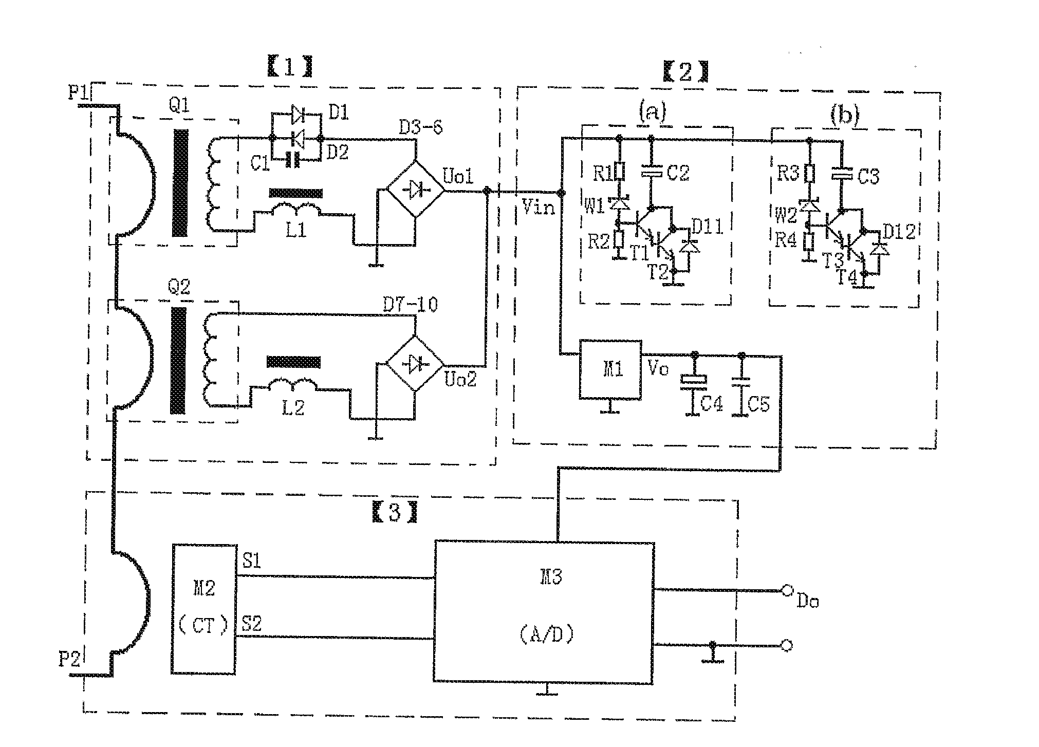
[0012]As shown in FIG. 1, the electronic current transformer based on complete self-excitation power supply provided in this embodiment includes: an energy-obtaining coil 1, a voltage-stabilizing circuit 2 and an A / D converting circuit 3. The output of the energy-obtaining coil 1 is connected with the input of the voltage-stabilizing circuit 2. The output of the voltage-stabilizing circuit 2 is connected with the control end of the A / D converting circuit 3. The detailed steps are as follows.

[0013]The energy-obtaining coil 1 includes a first energy-obtaining branch and a second energy-obtaining branch; the first energy-obtaining branch includes an energy-obtaining coil Q1, a choke coil L1, a diode D1, a diode D2, a capacitor C1, and bridge rectification circuits D3-6; the energy-obtaining coil Q1 obtains energy from a power line alternating magnetic fi...


PUM

PropertyMeasurementUnit
thicknessaaaaaaaaaa
diameteraaaaaaaaaa
diameteraaaaaaaaaa

Abstract

An electronic current transformer (ECT) based on complete self-excitation power supply is provided. The ECT includes an energy-obtaining coil, a rapid voltage-stabilizing circuit and an Analog / Digital (A / D) converting circuit. The output of the energy-obtaining coil is connected with the input of the voltage-stabilizing circuit. The output of the voltage-stabilizing circuit is connected with the control end of the A / D converting circuit. The ECT uses two branch circuits to obtain energy directly from the magnetic field of a bus bar to be measured respectively, synthesizes two output waveforms to fill the wave trough of each other, and reduces the pulse of direct current. In this way, the trough voltage of the synthesized wave is higher than the required stabilizing value of direct voltage and it directly meets the input requirement of the stabilizing module of the voltage-stabilizing circuit. As a result, the ECT can activate the A / D converting circuit rapidly. The present invention has solved the delay problem caused by using a single coil to obtain energy, and has characteristics of small wake-up current, rapid activation and wide application. The ECT can omit additional laser power supply device, simplify the architecture, improve the reliability of operation and service life, and reduce the cost.

Description

TECHNICAL FIELD[0001]The present invention relates to electric power measurement fields, and more particularly to an electronic current transformer.BACKGROUND ART[0002]In recent years, the oil-gas insulation system has been replaced by optical isolation technologies in high voltage and extra-high voltage electronic current transformers, so that the insulation technology of new type transformer has achieved a substantial development. The key for implementing such technology development is that, there are optical fiber communications between the high voltage side and low voltage side, and a power supply for a digital circuit is required to be set at the high voltage side, so as to digitize the magnitude of current; this is the biggest technical problem confronted during the manufacturing of the electronic transformer. At present, the method of transporting laser energy from the low voltage side to the high voltage side via the optic cable is generally adopted by domestic and foreign r...

Claims


Application Information

Patent Timeline
Patent Type & Authority Applications(United States)
IPC IPC(8): H01F38/28G01R15/18H02M7/06
CPCH01F38/28G01R15/18
Inventor LIU, ZHONGZHANWU, XUNSONG, YANTING
Owner XIAN HWELL OPTIC ELECTRIC TECH
Why Eureka
Try Eureka