Lens system

Inactive Publication Date: 2012-06-21
CANON KK
View PDF3 Cites 5 Cited by
  • Summary
  • Abstract
  • Description
  • Claims
  • Application Information

AI Technical Summary

Benefits of technology

[0014]According to the present invention, only in the case where one of the difference between the positional command value and the lens position and the difference between the speed command value and the drive speed exceeds the threshold set in the thresh

Problems solved by technology

However, demands for a small, lightweight and inexpensive camera impose a limitation on the capacity of power supply capable of being continuously supplied to the lens.
In other hand, the capacity of power supply capable of being continuously supplied from the camera to the lens held by this camera is limited to the same capacity as the conventional level.
Accordingly, in a case of simply increasing the maximum value of the drive current, the capacity of power supply from the camera is exceeded, w

Method used


Image

  • Lens system
  • Lens system
  • Lens system

Examples


embodiment 1

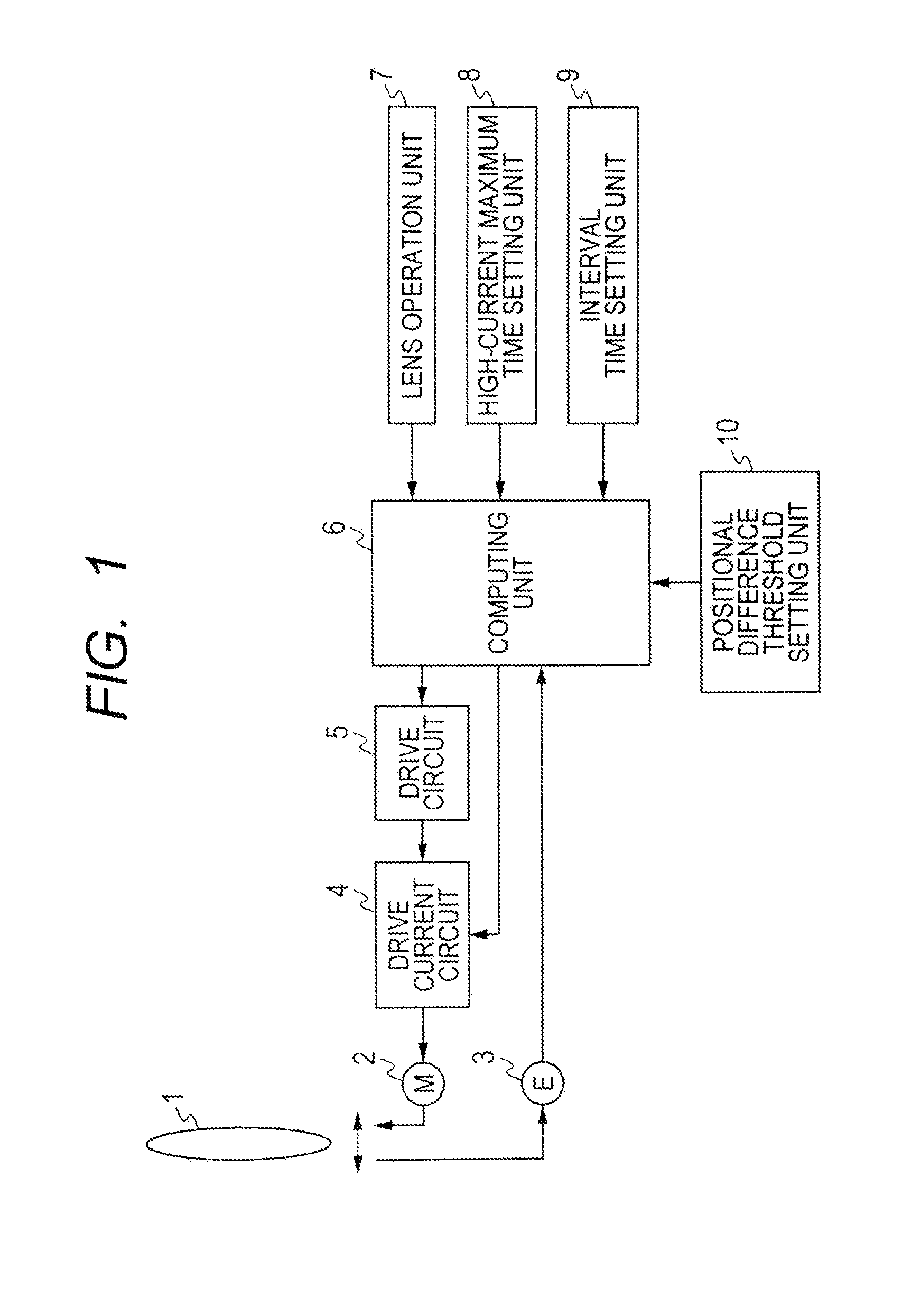
[0024]Hereinafter referring to FIG. 1, a configuration of a lens system of a first embodiment of the present invention is described.

[0025]The lens system of this embodiment includes a lens unit 1, a motor 2 that is a drive unit for driving the lens unit 1 and a position detector 3 for detecting the position of the lens unit 1 in the optical axis direction. The lens system further includes a drive circuit 5 that generates a drive signal for driving the motor 2, and a computing unit 6 that performs computations for controlling the drive of the motor 2. The computing unit 6 outputs a lens operation signal according to an operation by an operator on the lens operation unit 7; the operation corresponds to a drive amount of the lens unit 1 as an object to be driven. A drive current circuit 4 supplies a drive current to the motor 2 based on the drive signal from the drive circuit 5. The drive current circuit 4 can set any one of a first maximum current value serving as a normal state and a...

embodiment 2

[0039]Hereinafter referring to FIG. 3, a configuration of a lens system of a second embodiment of the present invention is described.

[0040]In the lens system of this embodiment, a lens unit 1, a motor 2 that is a drive unit for driving the lens unit 1, a position detector 3 for detecting the position of the lens unit 1 in the optical axis direction, a drive current circuit 4, a drive circuit 5 that generates a drive signal for driving the motor, a computing unit 6 for performing control computation for driving the motor, and a lens operation unit 7 that operates the lens unit 1 as an object to be driven are the same as those in the first embodiment. Accordingly, description thereof is omitted.

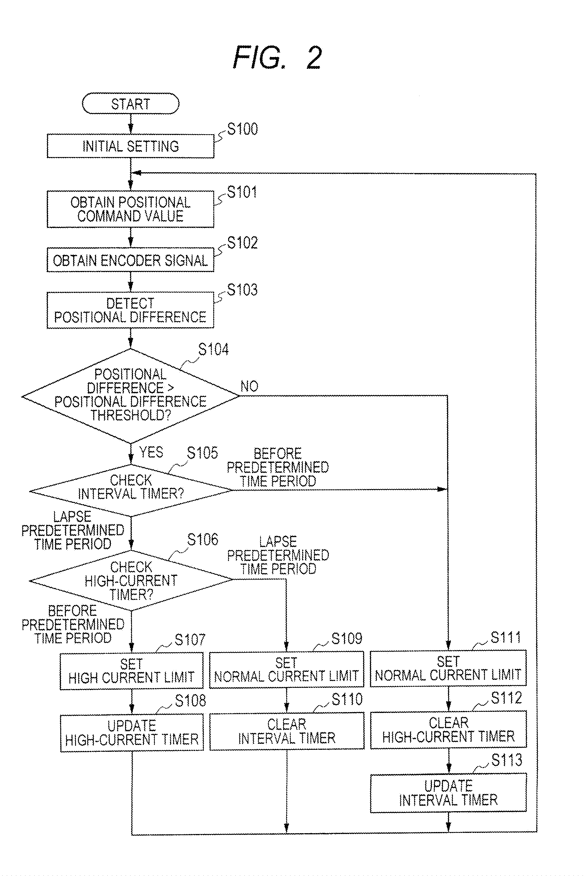
[0041]A high-current maximum time that is time during which the maximum current limit for the drive current circuit 4 can continuously be set to the second maximum current value larger than the normal state, and the minimum interval time required to be elapsed between a moment when the maximum ...

embodiment 3

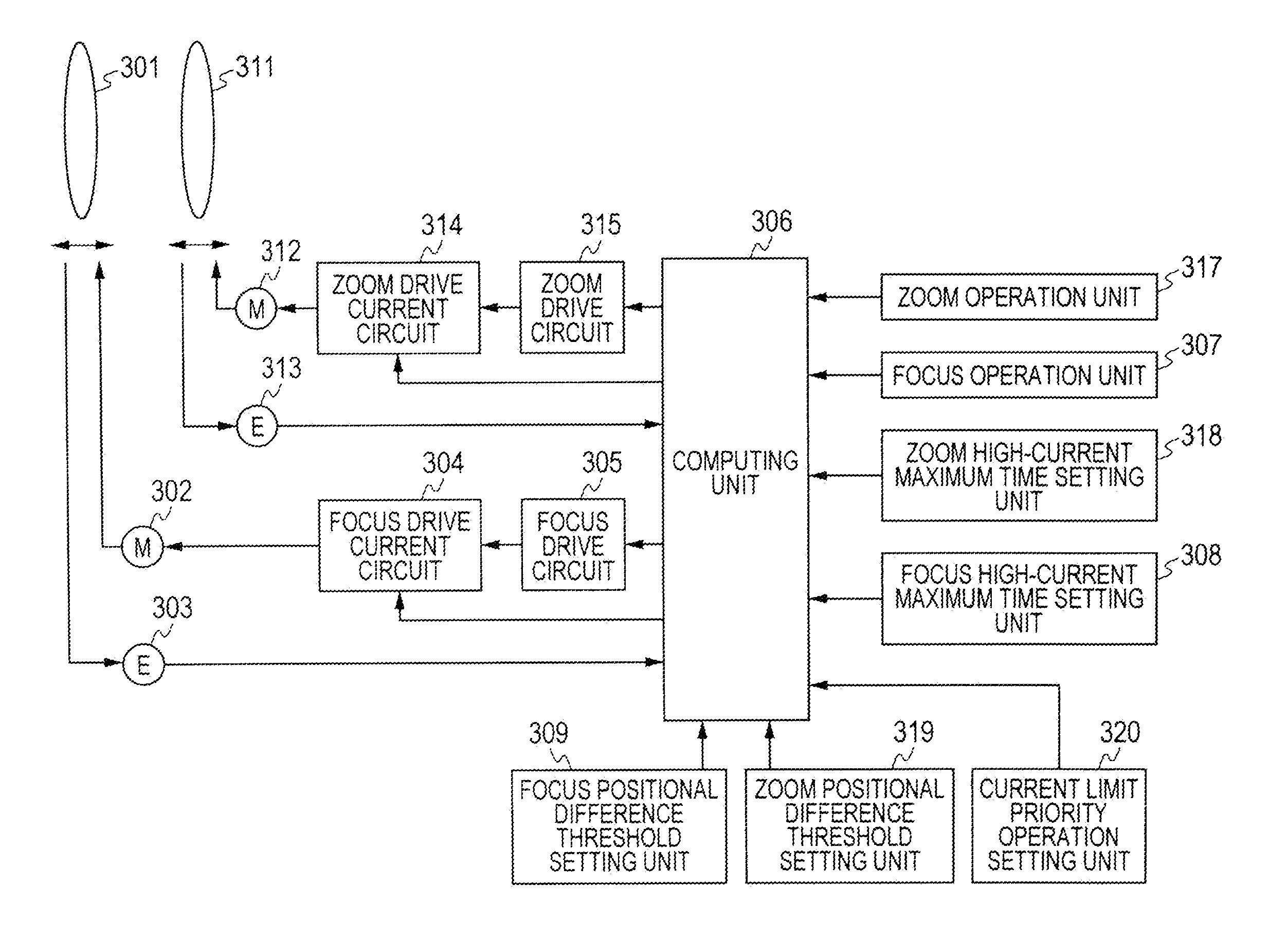
[0056]Hereinafter referring to FIG. 5, a configuration of a lens system of a third embodiment of the present invention is described.

[0057]The lens system of the third embodiment includes a focus lens unit 301 that conducts a focusing function, and a zoom lens unit 311 that conducts a zoom function. The focus lens unit 301 is driven by the focus motor 302. The position of the focus lens unit 301 in the optical axis direction is detected by a focus position detector 303. A focus drive current circuit 304 selects a maximum value of current to be supplied to the focus motor 302 for driving the focus lens unit 301 according to a selection signal output from an after-mentioned computing unit 306. The focus drive circuit 305 as a focus drive unit generates a drive signal for driving the focus motor 302.

[0058]Likewise, the zoom lens unit 311 is driven by a zoom motor 312. The position of the zoom lens unit 311 in the optical axis direction is detected by the zoom position detector 313. A zo...


PUM


Abstract

A lens system includes: a lens unit; a drive unit driving the lens unit in an optical axis direction; a detector detecting a position of the lens unit; a lens operation unit that operates driving of the lens unit; and a computing unit that computes a positional command value for controlling driving of the lens unit based on a signal input from the lens operation unit and controls driving of the lens unit; a time setting unit; and a threshold setting unit setting a positional difference threshold for switching the first and second current values set in the drive unit. When the difference between the positional command value and the lens position is larger than the positional difference threshold and duration after the second current value is set has not exceeded the high-current maximum time, the second current value is set. In other cases, the first current value is set.

Description

BACKGROUND OF THE INVENTION[0001]1. Field of the Invention[0002]The present invention relates to lens systems, such as a television lens and a video lens, that allow taking moving images.[0003]2. Description of the Related Art[0004]As to the lens systems that are used for a television lens and a video lens and allow taking moving images, there are many cases where a zoom lens unit conducting a zooming function and a focus lens unit conducting a focusing function are electrically driven using a motor in view of ease of operation for image taking and compatibility with a function to which an auto focus function is added.[0005]In such a lens system, power supply to be consumed on a lens side is supplied from a camera, which the lens system is mounted on or incorporated with, to this lens system. In such a system, on the camera side, it is necessary to secure a capacity of power supply to be consumed on the lens side in addition to a capacity of power supply required to operate a functi...

Claims


Application Information

Patent Timeline
IPC IPC(8): G02B7/09G02B7/02
CPCG02B7/102G03B3/10H04N5/23296H04N5/23212G03B13/04H04N23/67H04N23/69
Inventor KASUYA, JUNICHI
Owner CANON KK
Why Eureka
Try Eureka