Power feeding device, power receiving device, and wireless power feed system

a technology of power receiving device and power feeding device, which is applied in the direction of electric generator control, process and machine control, instruments, etc., can solve the problem of lowering the efficiency of power transfer and achieve the effect of high power transfer efficiency

Active Publication Date: 2012-06-28
SEMICON ENERGY LAB CO LTD
View PDF2 Cites 27 Cited by
  • Summary
  • Abstract
  • Description
  • Claims
  • Application Information

AI Technical Summary

Benefits of technology

[0045]In accordance with one embodiment of the disclosed invention, a wire

Problems solved by technology

However, with a wireless power feed system technique using a resonance method, the efficiency of power transfer is lowered when t

Method used


Image

  • Power feeding device, power receiving device, and wireless power feed system
  • Power feeding device, power receiving device, and wireless power feed system
  • Power feeding device, power receiving device, and wireless power feed system

Examples


embodiment 1

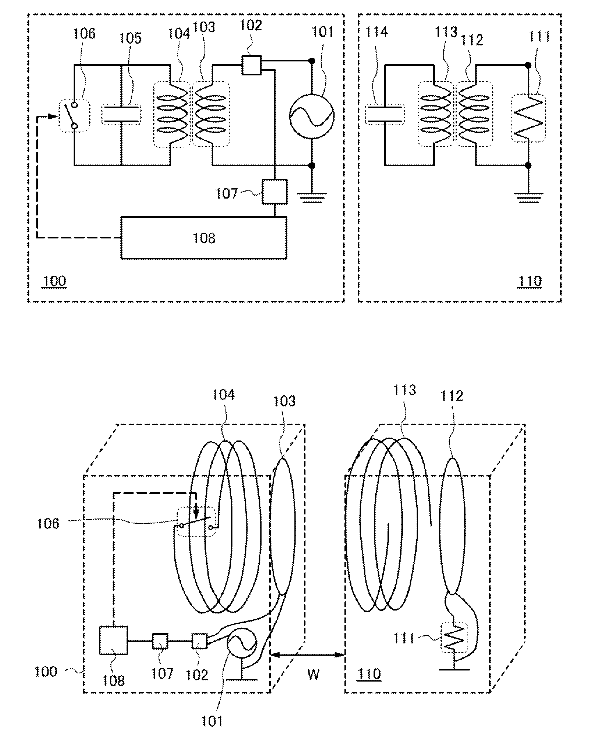
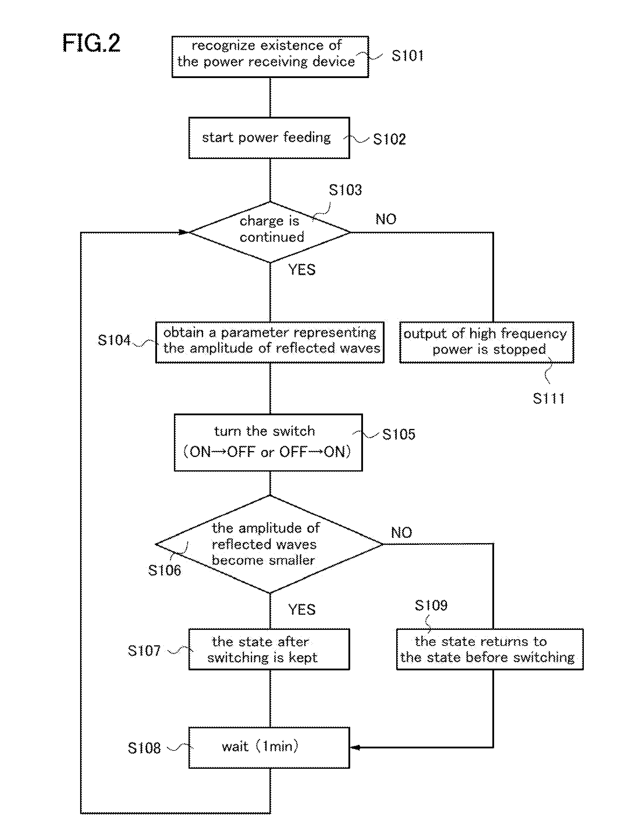
[0054]A wireless power feed system in this embodiment is illustrated in FIG. 1A and FIG. 1B. FIG. 1A is a circuit diagram of the wireless power feed system, while FIG. 1B is a perspective view of a part of the wireless power feed system.

[0055]The wireless power feed system illustrated in FIG. 1A and FIG. 1B includes a power feeding device 100 and a power receiving device 110. In this embodiment, the distance between the power feeding device 100 and the power receiving device 110 is set as a distance W.

[0056]The power feeding device 100 includes an AC power source 101, a directional coupler 102, an electromagnetic coupling coil 103, a resonant coil 104, a capacitor 105, a switch 106, an analog-digital converter (A / D converter) 107, and a control circuit 108. On the other hand, the power receiving device 110 includes a load 111, an electromagnetic coupling coil 112, a resonant coil 113, and a capacitor 114.

[0057]The AC power source 101 is a power source that outputs a high frequency p...

embodiment 2

[0102]in this embodiment, applications of the wireless power feed system described in Embodiment 1 can be described. Application examples of a wireless power feed system in accordance with one embodiment of the disclosed invention are mobile telephones, digital video cameras, computers, portable information terminals (such as mobile computers, mobile telephones, portable game consoles, or electronic books), image reproduction devices provided with a recording medium (specifically, a digital versatile disc (DVD)), and the like, which are portable electronic devices. Further, electric propulsion vehicles such as electric vehicles, which get power based on electricity can be given. Below, some examples will be described with reference to drawings.

[0103]FIG. 5A is an example in which a mobile phone and a portable information terminal use a wireless power feed system, and which includes a power feeding device 701, a mobile phone 702A including a power receiving device 703A, and a portabl...


PUM


Abstract

A wireless power feed system with high transfer efficiency of electric power is disclosed. The wireless power feed system includes a power feeding device and a power receiving device, wherein the power feeding device includes a first electromagnetic coupling coil that is connected to an AC power source via a directional coupler; a first resonant coil; a switch connected to the opposite ends of the first resonant coil; a control circuit which conducts switching on/off of the switch based on a parameter of an amplitude of a reflective wave detected by the directional coupler; and an analog-digital converter provided between the first electromagnetic coupling coil and the control circuit; and the power receiving device includes a second resonant coil; and a second electromagnetic coupling coil, and wherein the first electromagnetic coupling coil is provided between the first resonant coil and the second resonant.

Description

BACKGROUND OF THE INVENTION[0001]1. Field of the Invention[0002]One embodiment of the disclosed invention herein relates to power feeding devices, power receiving devices, and wireless power feed systems.[0003]2. Description of the Related Art[0004]Various electronic devices have spread, and a variety of products are in the marketplace. In recent years, mobile electronic devices such as mobile phones and digital video cameras are used very commonly. Further, electric propulsion vehicles; such as electric vehicles, which are supplied with power based on electricity, are showing up in the market.[0005]In such mobile phones, digital video cameras or electric propulsion vehicles, batteries serving as power storage units (referred to as storage batteries) are incorporated. Currently, such a battery is usually charged with use of a household AC power source that is one of power feeding units, and by being, directly contacted with the AC power. In a structure which has no battery or which ...

Claims


Application Information

Patent Timeline
IPC IPC(8): H02J17/00
CPCH02J5/005H02J50/12H02J50/50H02J50/90Y02E60/10H03M1/12B60L53/12H01F38/00H02J5/00H02J50/502
Inventor KAMATA, KOICHIROSATO, MISAKOMAEDA, SHUHEI
Owner SEMICON ENERGY LAB CO LTD
Why Eureka
Try Eureka