Liquid-crystal display

a liquid crystal display and display technology, applied in the field of liquid crystal display, can solve the problems of reducing the transparency of light, the strong viewing angle dependence of contrast, and the lengthening of response times

Active Publication Date: 2012-06-28
MERCK PATENT GMBH
View PDF8 Cites 32 Cited by
  • Summary
  • Abstract
  • Description
  • Claims
  • Application Information

AI Technical Summary

Benefits of technology

[0055]The terms “tilt” and “tilt angle” refer to a tilted or inclined orientation of the LC molecules in an LC mixture or LC medium relative to the surface of the cell walls in an LC display. The tilt angle herein means the average angle (<90°) between the molecular long axes of the LC molecules (LC director) and the surface of the plane parallel substrates forming the LC cell. A low value of the tilt angle (i.e. a large deviation from 90°) herein corresponds to a large tilt. A suitable method for measuring the tilt angle is described in the example section. Unless stated otherwise, the tilt angle values as given above and below refer to this measurement method.
[0056]The term “reactive mesogen” or “RM” denotes a compound containing a mesogenic group and one or more functional groups which are s...

Problems solved by technology

However, these have the disadvantage of a strong viewing-angle dependence of the contrast.
Although this arrangement improves the viewing angle of the display, it results, however, in a reduction in its transparency to light.
For further improvement of the transparency to light, the separations between the slits and protrusions can be increased, but this in turn results in a lengthening of the response times. In the so-called PVA (patterned VA), protrusions are rendered completely superfluous in that both electrodes are structured by means of slits on the opposite sides, which results in increased contrast and improved transparency to light, but is technologically difficult and makes the display more sensitive to mechanical influences (tapping, etc.).
As can be demonstrated in test cells, the PSA method results in a pretilt in the cell.
However, it has been found that the LC mixtures and RMs known from the prior art still have some disadvantages on use in PSA displays.
Thus, not every desired soluble RM is also suitable for PSA displays, and it often appears difficult to find more suitable selection criteria than the direct PSA experiment with pretilt measurements.
However, the problem arises that not every combination of LC mixture and polymerisable component works is suitable for use in PSA displays since, for example, an inadequate tilt or no tilt at all is established or since, for example, the HR is inadequate for TFT display applications.
Another problem when manufacturing PSA displays ist the pre...

Method used


Image

  • Liquid-crystal display
  • Liquid-crystal display
  • Liquid-crystal display

Examples


example 1

[0337]The following nematic LC host mixture H1 is formulated:

CY-3-O215.00%Cl.p.+80.5CY-5-O4 8.00%Δn0.0909CCY-3-O3 9.00%Δε−3.4CCY-4-O2 5.50%ε∥3.7CPY-2-O2 9.00%γ1138CPY-3-O2 9.00%CCY-3-1 7.00%CCH-34 9.00%CCH-25 5.00%CCH-2311.00%CCH-301 5.00%CCH-31 6.00%PPGU-3-F 1.00%

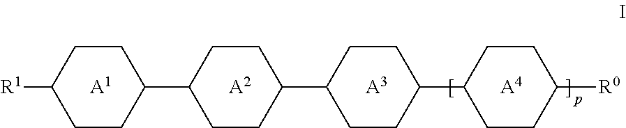
[0338]The mixture contains the compound PPGU-3-F of formula I selected from the first sub-group (dielectrically positive) and wherein p is 1.

example 2

[0339]The following nematic LC host mixture H2 is formulated:

CY-3-O215.00%Cl.p.+80.5CY-3-O410.00%Δn0.0912CCY-3-O2 6.50%Δε−3.3CCY-3-O3 9.00%ε∥4.2CCY-4-O2 8.00%γ1144CPY-2-O2 8.50%CPY-3-O2 6.00%CCH-34 9.00%CCH-25 5.00%CCH-2311.00%CCH-3013.00%CCP-31 6.00%PGU-3-F 3.00%

[0340]The mixture contains the compound PGU-3-F of formula I selected from the first sub-group (dielectrically positive) and wherein p is 0.

example 3

[0341]The following nematic LC host mixture H3 is formulated:

CY-3-O215.00%Cl.p.+80.0CY-3-O4 5.50%Δn0.0919CCY-3-O3 9.00%Δε−3.3CCY-4-O2 7.00%ε∥3.5CPY-2-O2 8.50%γ1125CPY-3-O2 9.00%CCY-3-1 3.00%CCH-34 9.00%CCH-25 5.00%CCH-2311.00%CCH-301 9.00%CCP-31 6.00%PGP-2-2V 3.00%

[0342]The mixture contains compound PGP-2-2V of formula I selected from the second sub-group (dielectrically neutral or negative) and wherein p is 0.


PUM

PropertyMeasurementUnit
Wavelengthaaaaaaaaaa
Fractionaaaaaaaaaa

Abstract

The present invention relates to the use of LC (liquid-crystal) compounds and LC media comprising them in LC displays of the PS (polymer stabilised) or PSA (polymer sustained alignment) type.

Description

[0001]The present invention relates to the use of LC (liquid-crystal) compounds and LC media comprising them in LC displays of the PS (polymer stabilised) or PSA (polymer sustained alignment) type.BACKGROUND OF THE INVENTION[0002]The LC displays used at present are mostly those of the TN (twisted nematic) type. However, these have the disadvantage of a strong viewing-angle dependence of the contrast.[0003]In addition, so-called VA (vertical alignment) displays are known which have a broader viewing angle. The LC cell of a VA display contains a layer of an LC medium between two transparent electrodes, where the LC medium usually has a negative value of the dielectric (DC) anisotropy. In the switched-off state, the molecules of the LC layer are aligned perpendicular to the electrode surfaces (homeotropically) or have a tilted homeotropic alignment. On application of an electrical voltage to the electrodes, a realignment of the LC molecules parallel to the electrode surfaces takes plac...

Claims


Application Information

Patent Timeline
IPC IPC(8): C09K19/02G02F1/13C09K19/32C09K19/34C09K19/30C09K19/12
CPCC09K19/12Y10T29/49117C09K2019/0448C09K2019/123C09K2019/124C09K2019/548C09K2019/3016C09K2019/3015C09K2019/301C09K2019/3009C09K2019/3004C09K19/542C09K19/3003G02F1/1334C09K19/44
Inventor LEE, SEUNG-EUNKIM, EUN YOUNGSONG, DONG-MEELEE, EUN-KYU
Owner MERCK PATENT GMBH
Why Eureka
Try Eureka