Illumination apparatus

a technology of illumination apparatus and light guide plate, which is applied in the direction of lighting and heating apparatus, planar/plate-like light guide plate, instruments, etc., can solve the problem of severe non-uniform light intensity distribution in the light guide plate, and achieve the effect of improving illumination efficiency and reducing unwanted light loss

Inactive Publication Date: 2012-06-28
KONINKLIJKE PHILIPS ELECTRONICS NV
View PDF20 Cites 8 Cited by
  • Summary
  • Abstract
  • Description
  • Claims
  • Application Information

AI Technical Summary

Benefits of technology

[0006]Considering the above problems found by the inventors of the present invention, it would be advantageous to provide for a substantially or comparatively uniform light distribution in the light guide plate, especially in the areas near the light source and far away from the light source. It would also be desirable to improve the illumination efficiency by decreasing the unwanted light loss caused by material absorption and light leakage.
[0011]The basic idea of the present invention is to confine the radiation direction of light within the light guide plate by using a build-in concentrator. When the preset plane is perpendicular to any one of the top surface and the bottom surface of the light guide plate and intersects the first surface and a second surface of the light guide plate, the incident light can radiate in straight lines from the first surface to the second surface and then less incident light is absorbed by the material of the light guide plate. When the preset plane is perpendicular to any one of the top surface and the bottom surface of the light guide plate and intersects the first surface and one side surface of the side surfaces at an angle that is substantially larger than the critical angle of a total reflection, most of the incident light will be totally reflected at the one side surface and less incident light leaks out of the light guide plate, especially at the side surfaces. In this way, unwanted light loss at the side surfaces of the light guide plate is decreased, and hence more incident light can radiate to the place in the light guide plate which is relatively far away from the light source. The distribution of the light intensity or luminance along the light guide plate is improved, i.e., a substantially uniform distribution of the light intensity can be achieved.

Problems solved by technology

The non-uniform light intensity distribution in the light guide plate is more severe when the light guide plate is longer.

Method used


Image

  • Illumination apparatus
  • Illumination apparatus
  • Illumination apparatus

Examples


Embodiment Construction

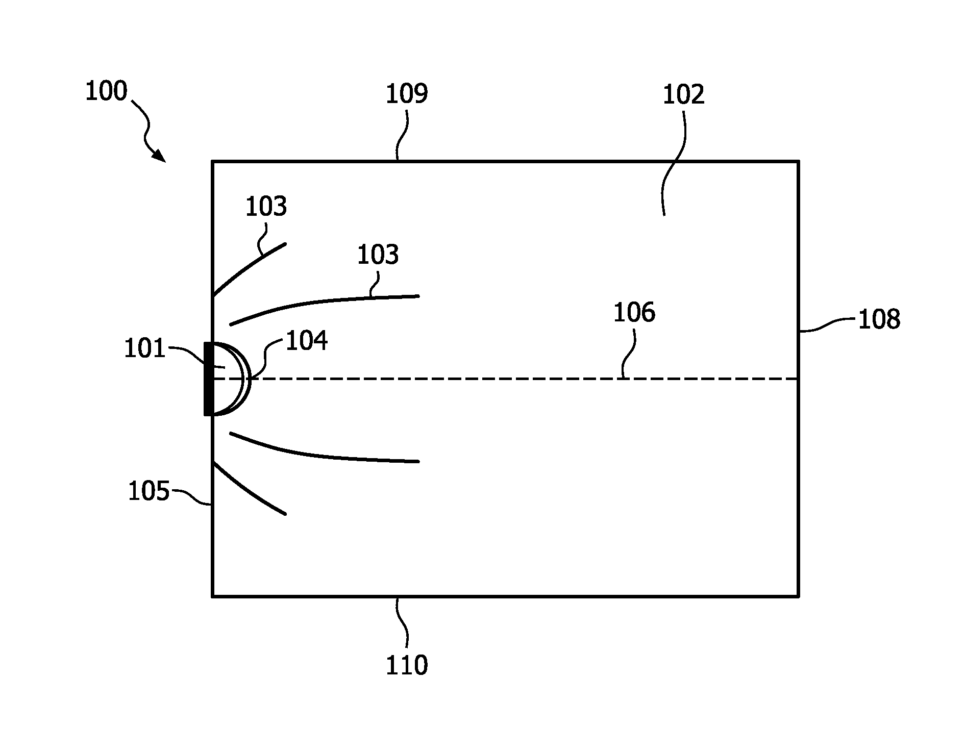
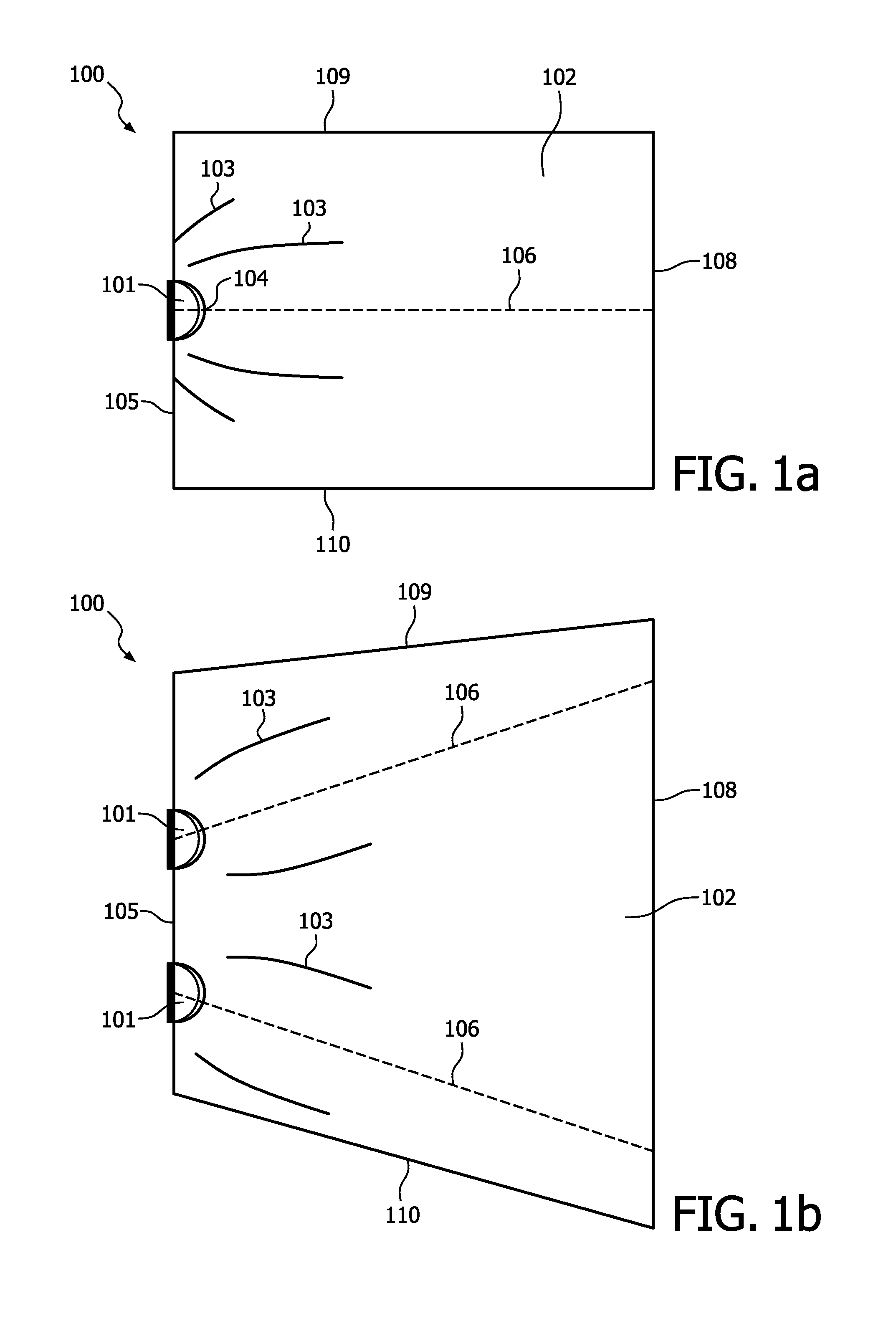
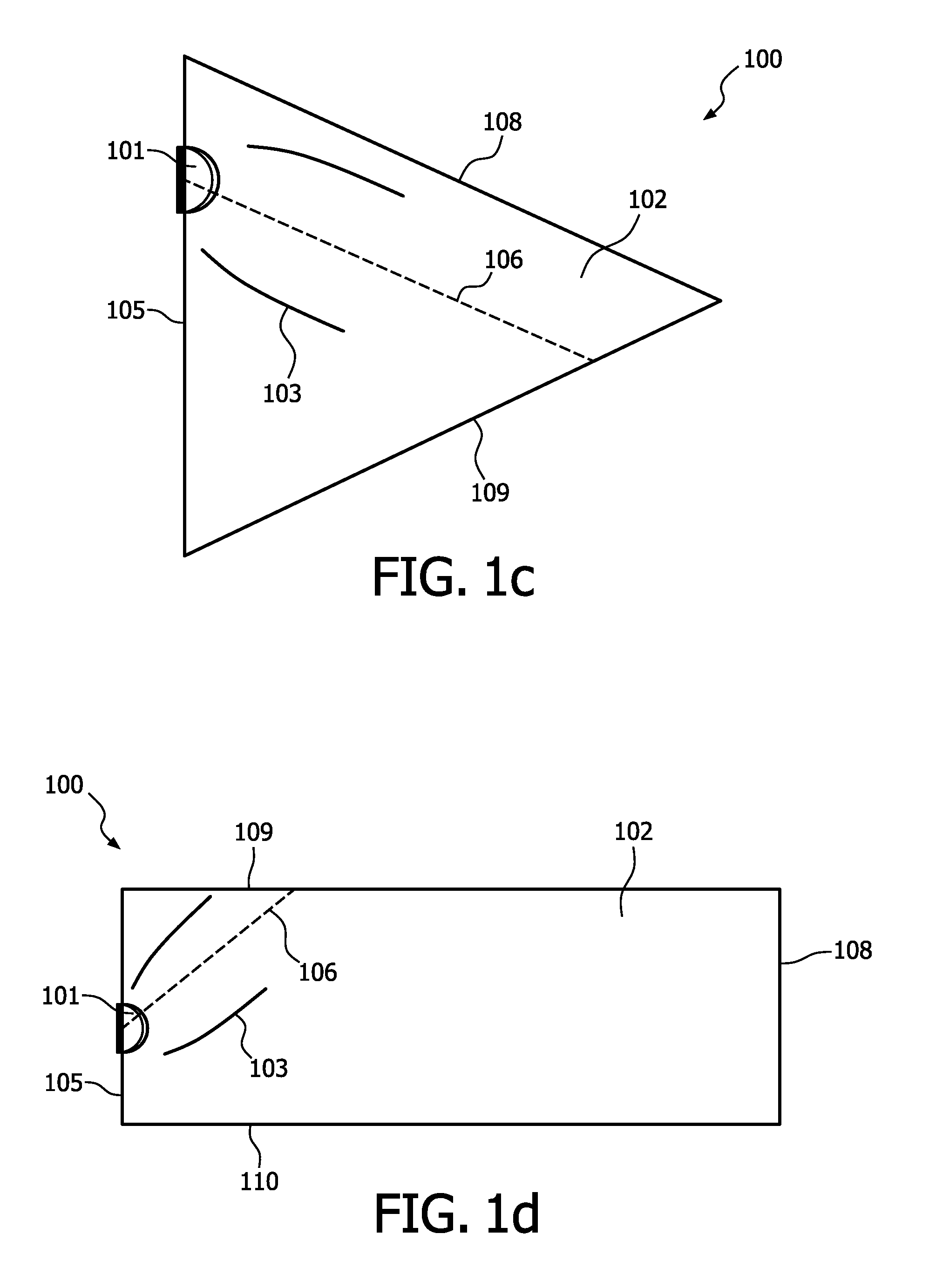
[0020]The present invention provides an illumination apparatus. Although the shape of the illumination apparatus is three-dimensional, for the sake of simplicity, most of the Figures in FIG. 1 to FIG. 5 are two-dimensional views of embodiments of the illumination apparatus.

[0021]FIG. 1 (a) to FIG. 1 (c) depict schematic diagrams of top views of embodiments of the illumination apparatus.

[0022]As shown in FIG. 1 (a), the illumination apparatus 100 comprises a light guide plate 102. The light guide plate 102 is a light conductive plate, which can be made from a material such as quartz, glass, transparent resin like acrylic resin or polycarbonate, or the like. The shape of the light guide plate 102 can be cuboid, trapezoid and triangular as shown respectively in FIG. 1 (a) to FIG. 1 (c), although other regular and irregular shapes are also possible. The light guide plate 102 can be thin or thick.

[0023]The illumination apparatus 100 further comprises a light source 101 configured to emit...


PUM


Abstract

This invention relates to an illumination apparatus. The illumination apparatus comprises a light guide plate and a light source configured to emit light into the light guide plate through a first surface, and the light guide plate comprises a concentrator configured to direct incident light in the light guide plate so as to radiate in a direction substantially parallel to a preset plane. The preset plane is perpendicular to any one of the top surface and bottom surface of the light guide plate, and intersects the first surface and a second surface of the light guide plate or intersects the first surface and one of the side surfaces at an angle that is substantially larger than the critical angle of a total reflection. In this way, unwanted light loss in the light guide plate is reduced, and the distribution of the light intensity or luminance along the light guide plate is improved, i.e., a substantially uniform distribution of the light intensity can be achieved.

Description

FIELD OF THE INVENTION[0001]The invention relates to an illumination apparatus, especially a space divider comprising illumination components.BACKGROUND OF THE INVENTION[0002]Light guide plates are widely used in many products, such as LCDs (Liquid Crystal Displays), ultra-thin light boxes and backlights of portable devices, etc. In different applications, the light guide plate cooperates with light sources to fulfill different kinds of illumination requirements.[0003]US2001 / 0019479 discloses an illuminating system. The illuminating system comprises a linear light source, and a light guide member with the light source placed beside a side face thereof, in which the top face and the bottom face of the light guide member are generally parallel to each other and in which slits made of a different material or air are arranged at specific intervals in the top face of the light guide member. Therefore, most of the light propagating within the light guide member is totally reflected at the...

Claims


Application Information

Patent Timeline
Patent Type & Authority Applications(United States)
IPC IPC(8): F21V7/00F21V7/07F21V7/04F21V7/08F21V8/00F21V7/06
CPCG02B6/0021G02B6/0016
Inventor BAKKER, LEVINUS PIETERSHE, JUNCORNELISSEN, HUGO JOHANWEI, GONGMING
Owner KONINKLIJKE PHILIPS ELECTRONICS NV
Why Eureka
Try Eureka