Method and a Touch Sensing Device for Implementing the Method

a touch sensing device and method technology, applied in the field of methods and touch sensing devices for implementing methods, can solve the problems of not always being able to identify all unwanted contributions, tedious and time-consuming activities, etc., and achieve the effect of reducing noise contributions, improving the signal-to-noise ratio of sensed signals, and reducing noise in signals

Active Publication Date: 2012-06-28
ELO TOUCH SOLUTIONS INC
View PDF1 Cites 12 Cited by
  • Summary
  • Abstract
  • Description
  • Claims
  • Application Information

AI Technical Summary

Benefits of technology

[0006]The object of the invention is achieved with the method for reducing noise in a signal sensing a bending wave propagating in an object comprising the steps of: a) receiving a sensed signal representative of a plurality of locations of the object, and b) fitting a function satisfying bending wave propagation properties to the sensed signals, thereby reducing noise contributions to the sensed signals not satisfying the bending wave propagation properties. Thereby noise not satisfying the physical principles underlying the wave propagation in an object is suppressed or at least reduced and thereby the signal-to-noise ratio of the sensed signals can be improved.
[0007]Preferably, the object is a uniform plate with a thickness less than the bending wave wavelength and step b) comprises fitting a function satisfying the Helmholtz equation to the sensed signal. Physical principles underling the wave propagation in such a uniform plate can be well approximated by the Helmholtz equation, but any other kind of approximations in the field of wave propagation could also be considered. In particular, the function used in step b) can be a Bessel function or an expansion of the Bessel function up to an nth order. Bessel functions solve the Helmholtz equation, thus physically meaningful fits can be carried out. Advantageously, the fitting can be carried out such that the bending wave dispersion relationk=ω[12(1-υ2)ρEh2]1 / 4,with ω being the angular frequency of the bending wave propagating in the object, E, υ and ρ being respectively the modulus of elasticity, the Poisson's ratio and the density of the object and h being the thickness of the object, is satisfied. By choosing the order up to which one wants to use the Bessel function expansion, it is possible to achieve the desired precision.
[0008]Advantageously, the fitting function can furthermore comprise a bending wave attenuation contribution. Thus an even more realistic model can be prepared to effectively reduce noise contributions not satisfying the physics of the wave propagation.
[0017]According to a preferred embodiment, the method further can comprise after step b), a step d) of replacing the sensed signals by the fitted values and a step e) of determining acoustic transfer functions for each location of the object for which a fitted value has been established in step b) with respect to the first transducer position. Thus improved calibration look-up tables can be achieved.

Problems solved by technology

This represents a tedious and time consuming activity and in addition it is not always possible to identify all unwanted contributions.

Method used


Image

  • Method and a Touch Sensing Device for Implementing the Method
  • Method and a Touch Sensing Device for Implementing the Method
  • Method and a Touch Sensing Device for Implementing the Method

Examples


first embodiment

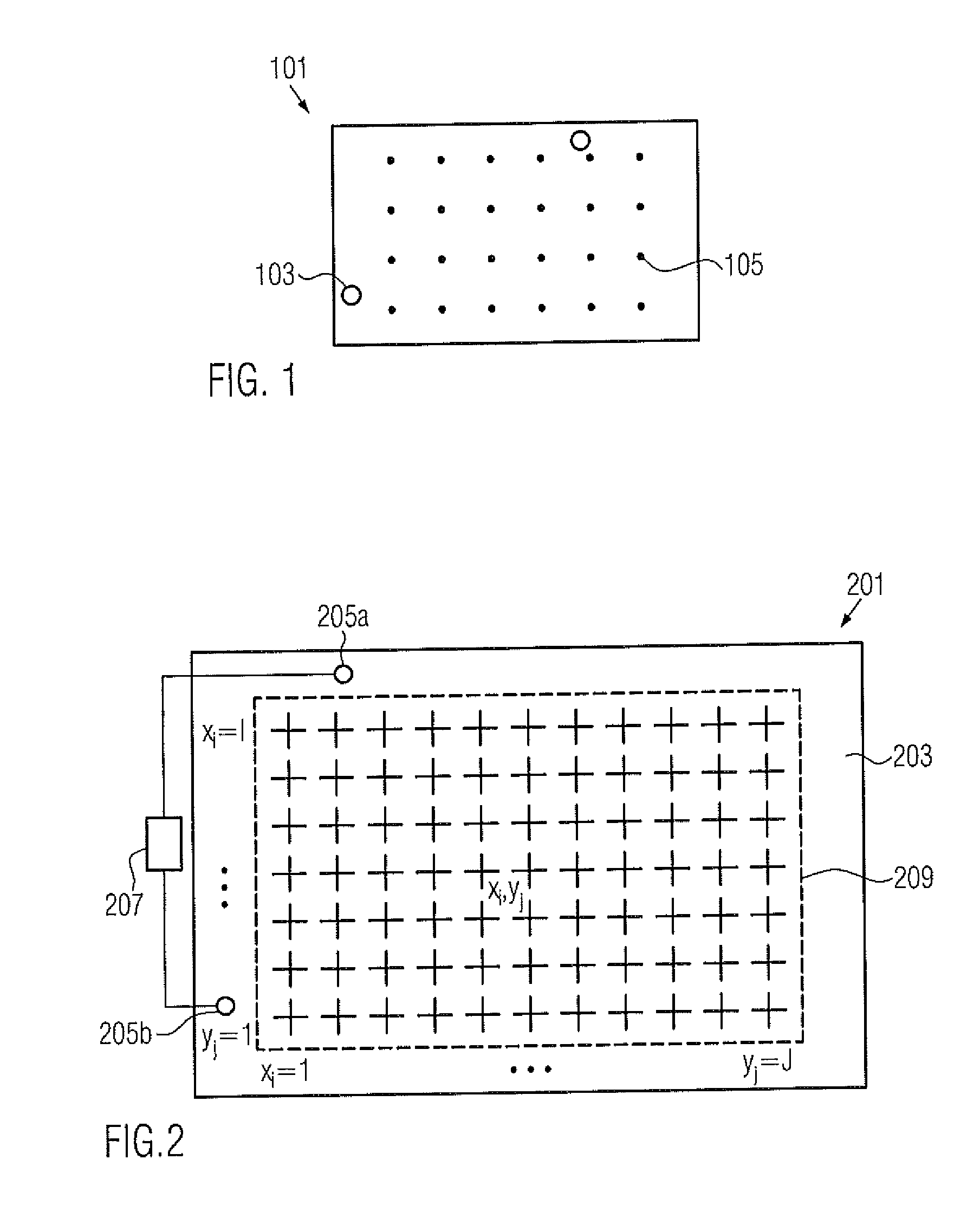
[0028]FIG. 2 illustrates a two-dimensional schematic view of a touch sensing device 201 using a method for reducing noise in a signal sensing a bending wave propagating in an object, here a touch sensing device 201, according to the invention.

[0029]The touch sensing device 201 comprises an interaction surface 203, e.g. a glass plate or the like, and at least one transducer 205. In this embodiment, the touch sensing device 201 comprises two transducers 205a, 205b, e.g. piezoelectric transducers, capacitive piezoelectric transducers, magnetostrictive piezoelectric transducers, electromagnetic piezoelectric transducers, acoustic velocimeters, accelerometers, optical sensors, MEMS or any device capable of transforming an acoustic signal into an electric one and visa versa. The coupling between the transducers 205a and 205b and the interaction surface 203 is achieved by a fastening means, which can be a tape, glue or the like. Depending on the configuration of the device, more than two ...

fifth embodiment

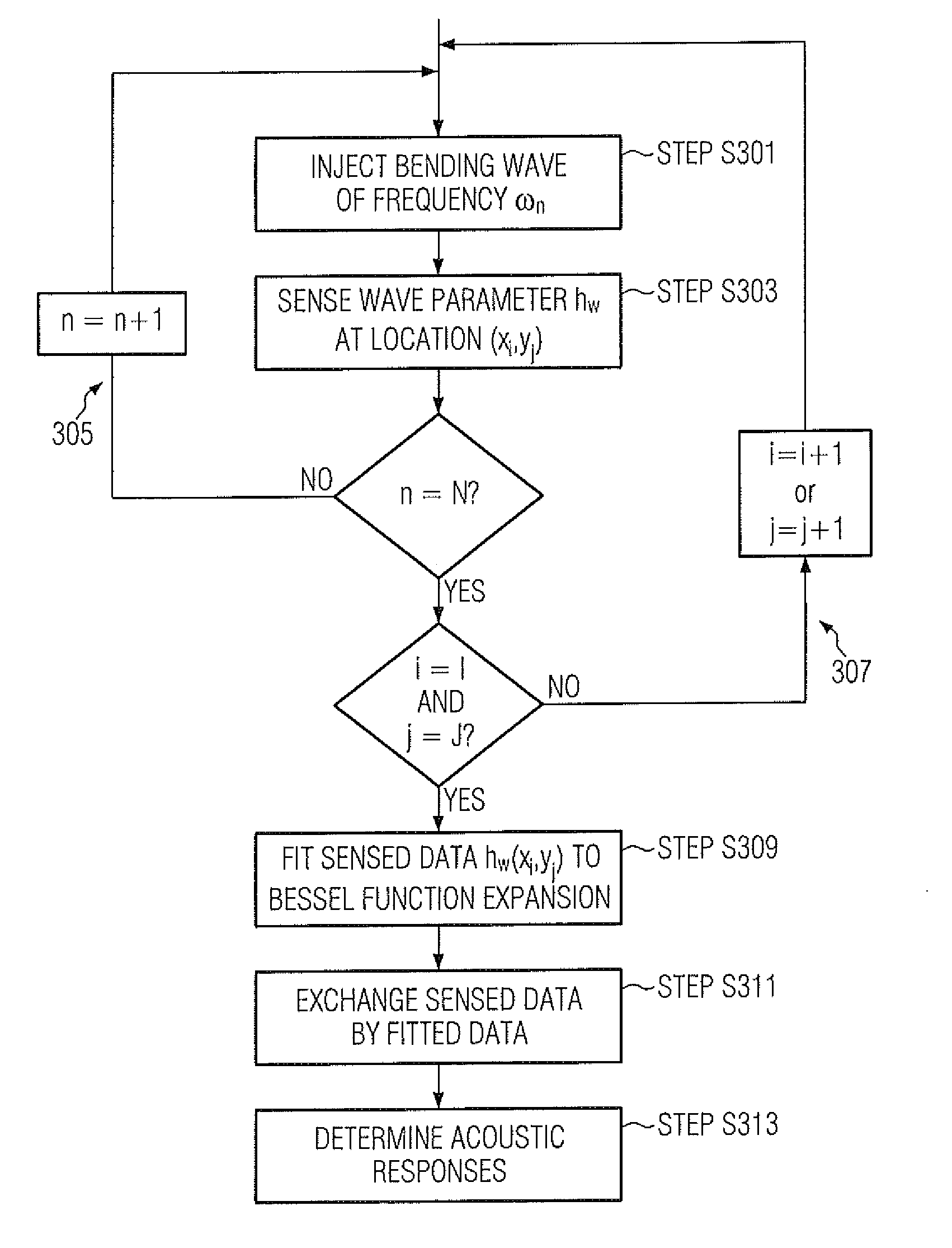
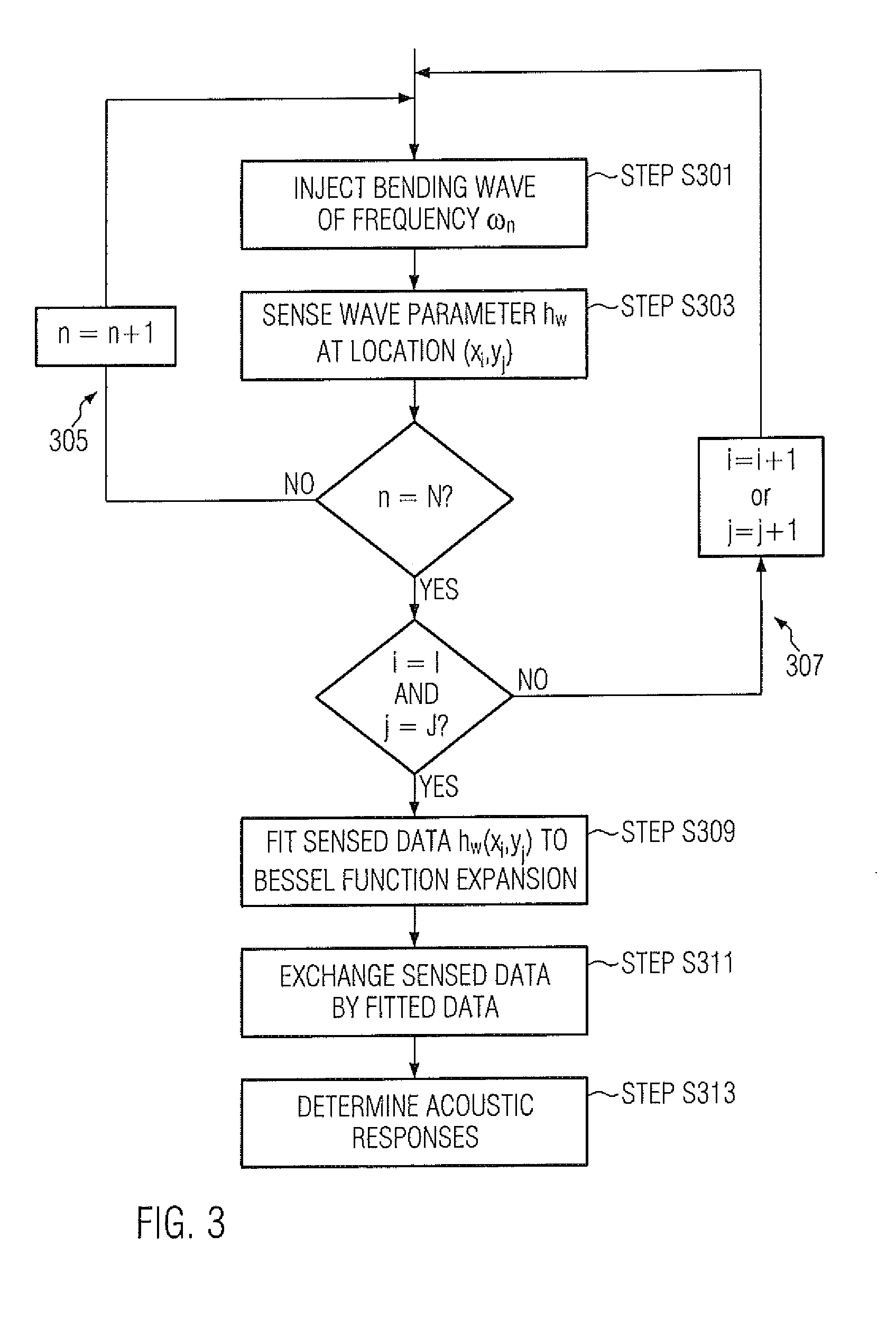
[0038]If hω(xi, yj) is measured at each calibration grid location (xi, yj), the inventive method proposes to reduce noise contributions in the measurement by fitting the measured data to a function that obeys the laws of physics underlying the acoustic wave propagation in the interaction surface 203. Using a function satisfying bending wave propagation properties to fit the measured data, noise contributions to the sensed signals not satisfying the bending wave propagation properties can be reduced.

[0039]In fact, the measured data has to obey the Helmholtz Equation which can be expressed as follows:

∂2hω / ∂X2+∂2hω / ∂Y2+k2hω(X,Y)=0  (1)

[0040]In an alternative notation, Helmholtz Equation can also be written as follows:

(∇2+k2)hω(X,Y)=0  (2)

[0041]The wave number k is determined by the bending wave dispersion relation given in Equation 7 as already mentioned above.

k=ω[12(1-υ2)ρEh2]1 / 4(3)

[0042]The Helmholtz Equation (2) and the dispersion relation (3) apply to bending waves propagating in ...

second embodiment

[0054]FIG. 5 illustrates a method for reducing noise in a signal sensing a bending wave propagation in an object according to a

[0055]The method according to the second embodiment can be carried out to establish calibration data of a touch sensitive device 201 as illustrated in FIG. 2. In contrast to the first embodiment, the second embodiment proposes not to inject bending waves using the transducers 205a and 205b of the touch sensor device 291, but to use a robotized calibration device, being a tool for applying a mechanical excitation to the interaction surface 203 at a grid location (xi, yj). The device can comprise a rigid tip, such as a pike or a small ball made of any rigid material such as metals or the like, to transmit a predetermined excitation tap upon the interaction surface 203. The device may further comprise a transducer to convert an electric signal into a mechanical excitation, such as an electromagnetic shaker, a piezoelectric transducer, capacitive piezoelectric t...


PUM


Abstract

The present invention relates to a method for reducing noise in a signal sensing a bending wave propagating in an object comprising the steps of: receiving a sensed signal representative of a plurality of locations of the object, and fitting a function satisfying bending wave propagation properties to the sensed signals, thereby reducing noise contributions to the sensed signals not satisfying the bending wave propagation properties. By doing so, noise contributions not satisfying the wave propagation properties can be suppressed from the sensed signal, thereby improving the signal-to-noise ratio.

Description

CROSS-REFERENCE TO RELATED APPLICATIONS[0001]This application is a continuation-in-part of U.S. patent application Ser. No. 12 / 975,663 filed Dec. 22, 2010, which is hereby incorporated in its entirety by reference for all purposes.BACKGROUND[0002]The present invention relates to a method for determining an acoustic response attributed to a location of an impact, like a touch event on a surface of an object, and a touch sensing device implementing the method.[0003]Methods to determine the location of an impact on a surface of an object based on analysing acoustic signals are already known in the art. This kind of technology is based on measuring the acoustic signal using one or more sensors to obtain an acoustic signature of the impact and to compare the signature with a predetermined set of acoustic signatures, wherein each predetermined acoustic signature is representative for a given location of the haptic or tactile interface. The location of the impact is then identified based o...

Claims


Application Information

Patent Timeline
Patent Type & Authority Applications(United States)
IPC IPC(8): G06F15/00
CPCG06F3/0433G06F3/0418
Inventor KENT, JOEL C.
Owner ELO TOUCH SOLUTIONS INC
Why Eureka
Try Eureka