Dynamic and selective core disablement and reconfiguration in a multi-core processor

Active Publication Date: 2012-06-28
VIA TECH INC
View PDF6 Cites 71 Cited by
  • Summary
  • Abstract
  • Description
  • Claims
  • Application Information

AI Technical Summary

Benefits of technology

[0006]In a related aspect, a kill-instruction-disabled core, because it is unresponsive to system bus transactions, does not respond to or comply with and is disabled from responding to or complying with

Problems solved by technology

But the disablement is, in practical (un-

Method used


Image

  • Dynamic and selective core disablement and reconfiguration in a multi-core processor
  • Dynamic and selective core disablement and reconfiguration in a multi-core processor
  • Dynamic and selective core disablement and reconfiguration in a multi-core processor

Examples


Embodiment Construction

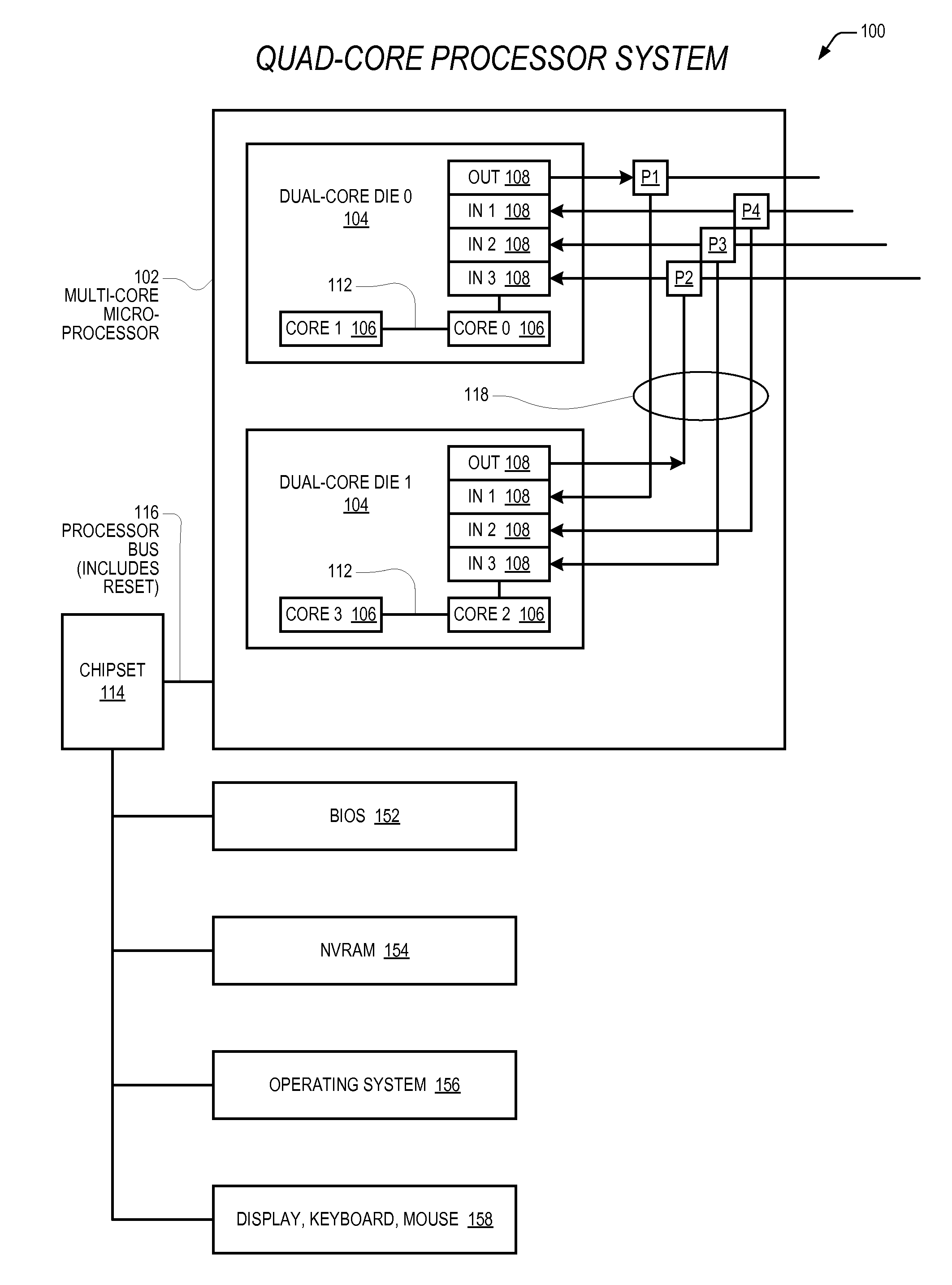
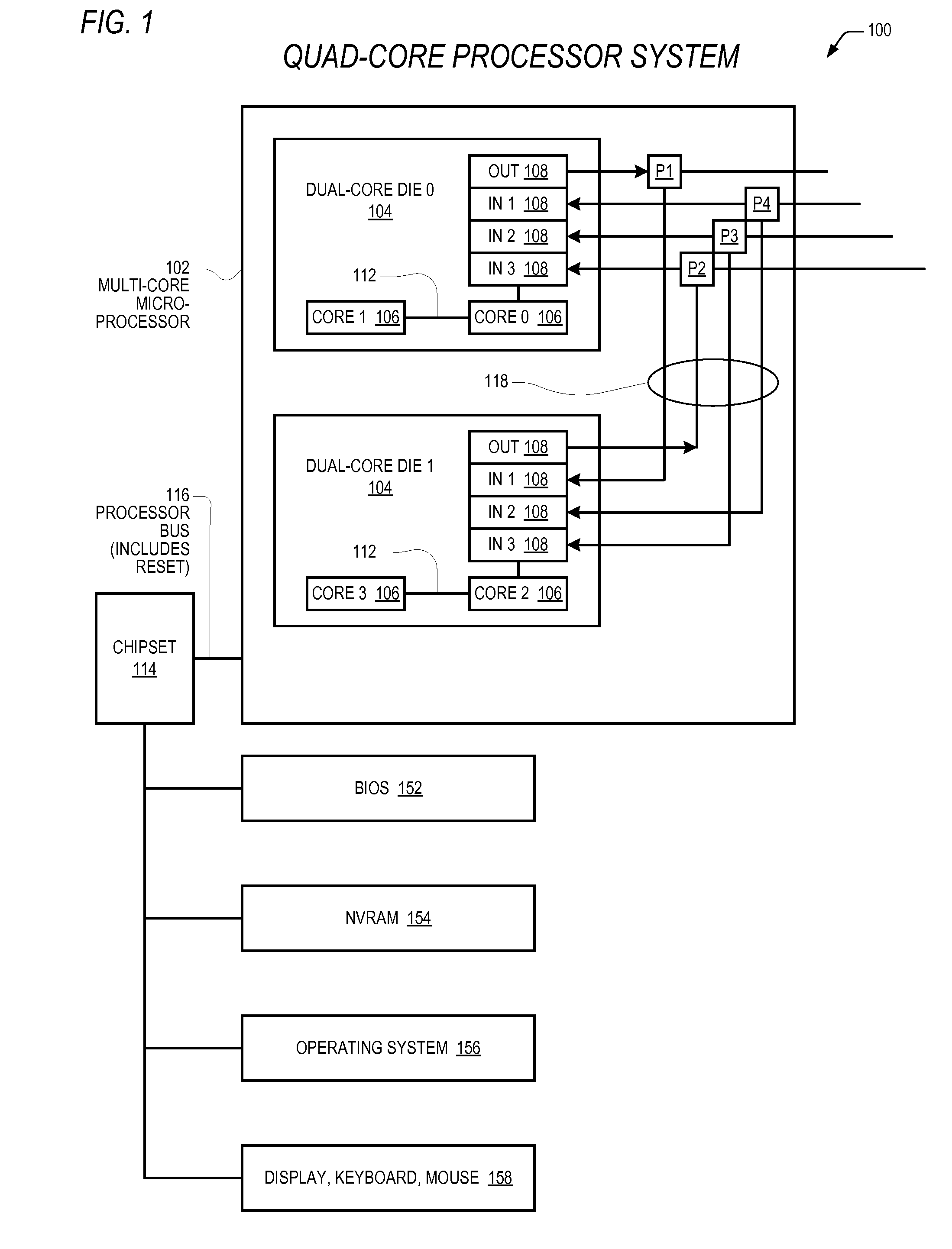
[0025]Described herein are embodiments of an apparatus and method for dynamically re-configuring the core configuration of a multi-core microprocessor. In one aspect, multi-core microprocessors and associated methods are provided that support the ability of system software (such as BIOS or an operating system) to disable, or kill, selected cores. Advantageously, the cores are killed in such a way that they do not cause drag on the processor bus shared with the other cores. This may be a desirable feature for performance testing or for software that does not support multiple cores, for examples. In another aspect, multi-core microprocessors and associated methods are provided that support a reconfiguration of an inter-core coordination system of the microprocessor. Advantageously, cores may be selectively designated as masters for purposes of driving signals onto an inter-core communication wire. In this way, a micro-processor may be configured to adapt and even be “self-healing,” fo...


PUM


Abstract

Dynamically reconfigurable multi-core microprocessors and associated methods are provided. A multi-core microprocessor is provided that supports the ability of system software to disable, or kill, selected cores in such a way that they do not cause drag on the processor bus shared with the other cores. Another multi-core microprocessor is provided that supports reconfiguration of an inter-core coordination system of the microprocessor, wherein cores may be selectively designated as masters for purposes of driving signals onto an inter-core communication wire.

Description

CROSS REFERENCE TO RELATED APPLICATION(S)[0001]This application claims priority based on U.S. Provisional Application, Ser. No. 61 / 426,470, filed Dec. 22, 2010, entitled MULTI-CORE INTERNAL BYPASS BUS, which is hereby incorporated by reference in its entirety.[0002]This application is related to the following co-pending U.S. Patent Applications which are concurrently filed herewith, each of which is hereby incorporated by reference in its entirety.SerialFilingNumberDateTitleTBDhere-MULTI-CORE INTERNAL BYPASS BUS(CNTR.2503)withTBDhere-POWER STATE SYNCHRONIZATION IN A(CNTR.2518)withMULTI-CORE PROCESSORTBDhere-DECENTRALIZED POWER MANAGEMENT(CNTR.2527)withDISTRIBUTED AMONG MULTIPLEPROCESSOR CORESTBDhere-RETICLE SET MODIFICATION TO PRODUCE(CNTR.2528)withMULTI-CORE DIESTBDhere-DYNAMIC MULTI-CORE MICRO-(CNTR.2533)withPROCESSOR CONFIGURATION DISCOVERYTBDhere-DISTRIBUTED MANAGEMENT OF A(CNTR.2534)withSHARED POWER SOURCE TO A MULTI-CORE MICROPROCESSORFIELD OF THE INVENTION[0003]The present in...

Claims


Application Information

Patent Timeline
IPC IPC(8): G06F9/318G06F9/02G06F15/76
CPCG06F11/3664G06F9/5094G06F9/30076G06F9/30083G06F15/82G06F1/3287G06F1/24Y02B60/142G06F9/44505G06F11/1423G06F13/36Y02D10/00G06F1/26G06F1/3243G06F15/163
Inventor HENRY, G. GLENNGASKINS, STEPHAN
Owner VIA TECH INC
Why Eureka
Try Eureka