
Rope-controlled structure for extended reach garden shears

a technology of extended reach and garden shears, which is applied in the field can solve the problems of difficult trimming action and rough operation of extended reach garden shears, and achieve the effects of facilitating use, and reducing the movement distance of handgrips

Inactive Publication Date: 2012-07-05
HO CHENG GARDEN TOOLS
View PDF5 Cites 22 Cited by
  • Summary
  • Abstract
  • Description
  • Claims
  • Application Information

AI Technical Summary

Benefits of technology

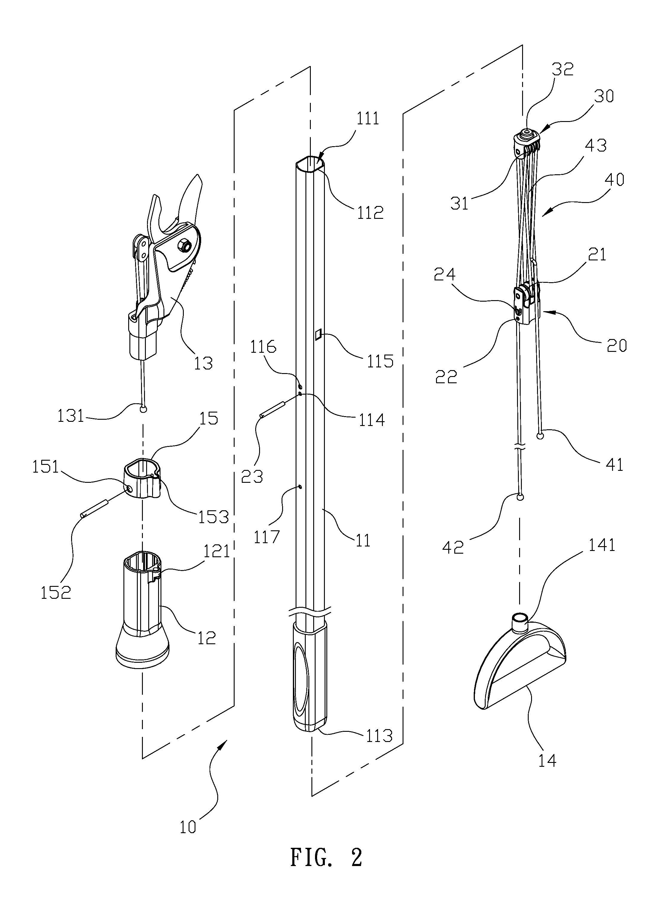
[0010]In order to achieve the above objective, the present invention provides a rope-controlled structure for extended reach garden shears. The extended reach garden shears are provided with an extension rod. The extension rod is provided with a fixed base and a movable base. The fixed base is provided with a plurality of rollers, and the movable base is provided with a plurality of pulleys. A rope wraps around the rollers of the fixed base and the pulleys of the movable base. The pulling of the rope causes the movable base to slide. In this way, a cutting head of the extended reach garden shears performs a trimming action. The connection among the rope, the fixed base and the movable base controls the trimming action of the extended reach garden shears in a labor-saving manner.
[0011]According to another feature of the present invention, the extension rod is fixedly provided with a restricting sleeve, and the restricting sleeve is provided with a guide hole through which the rope is disposed. The guide hole of the restricting provides a smoother action for the handgrip when pulling the rope. The restricting sleeve is stopped between the rope-guiding hole and the handgrip, thereby restricting the moving distance of the handgrip and facilitating usage of the present invention.
[0012]According to another feature of the present invention, when the fixed base is disposed into the extension rod, a protrusion on the fixed base engages with a locking hole in the extension rod, so that a through-hole of the fixed base aligns with a pin hole of the extension rod. In this way, a pin can be disposed through the pin hole and the through-hole easily, thereby facilitating assembly of the present invention.

Problems solved by technology

However, the above-mentioned conventional garden shears have the following problems.
As a result, the user has to pull the sliding handgrip 51 with a greater force, which makes the trimming action difficult.
As a result, the rope-guiding portion 53 can collide with the sliding handgrip 51 and suffer damage thereby, which makes the operation of the extended reach garden shears rough.

Method used


Image

  • Rope-controlled structure for extended reach garden shears
  • Rope-controlled structure for extended reach garden shears
  • Rope-controlled structure for extended reach garden shears

Examples


Embodiment Construction

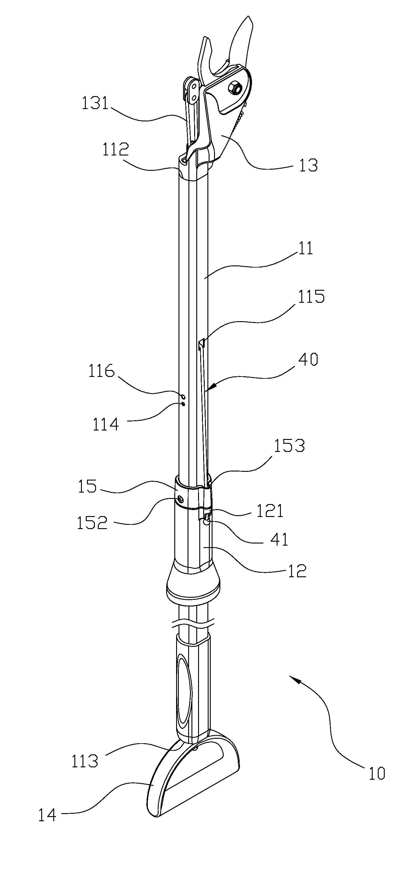
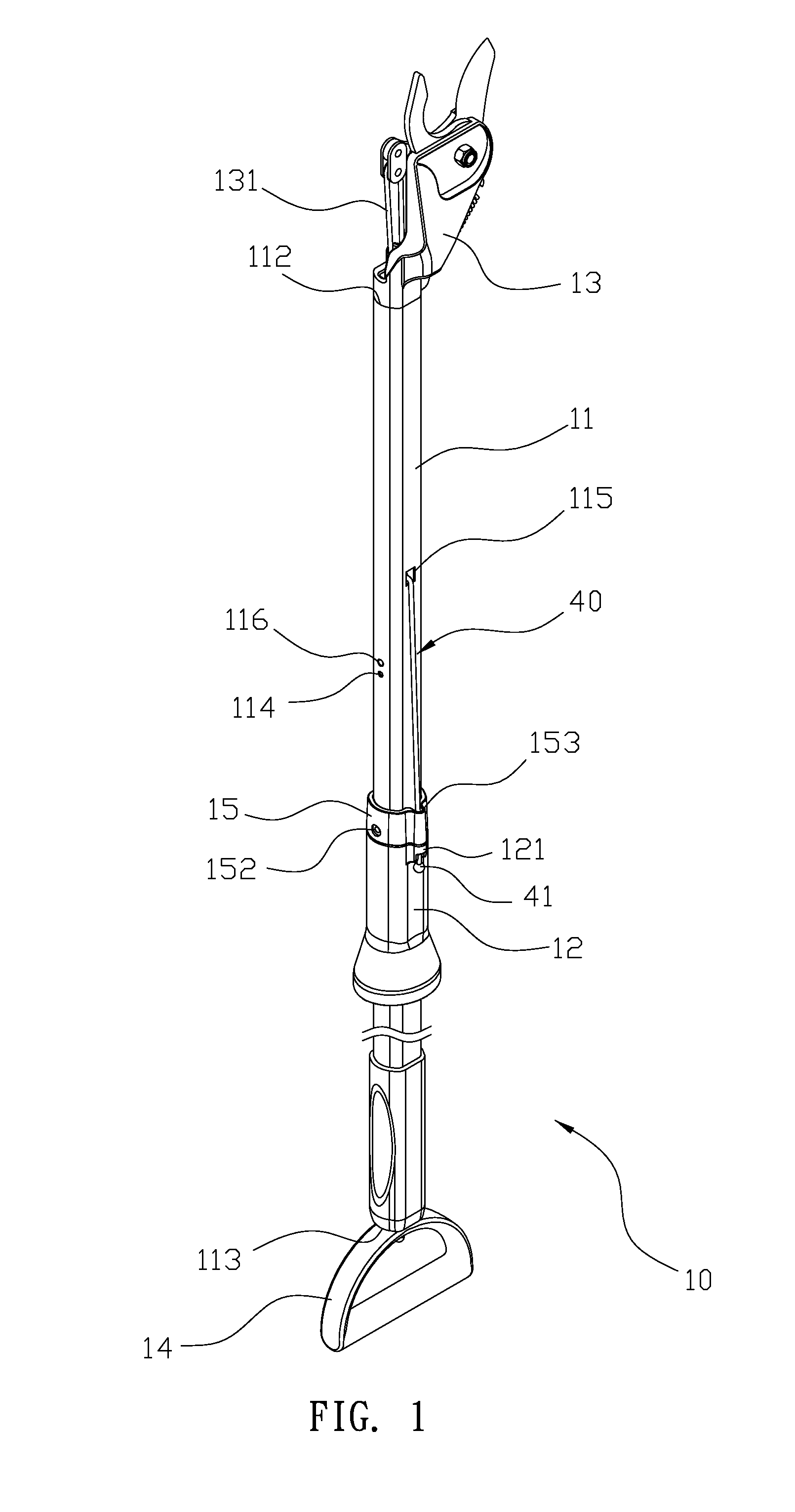
[0021]Please refer to FIGS. 1 to 3. An embodiment of the present invention provides a rope-controlled structure for extended reach garden shears, which includes extended reach garden shears 10, a fixed base 20, a movable base 30 and a rope 40. The fixed base 20 and the movable base 30 are mounted within the extended reach garden shears 10. The rope 40 wraps between the fixed base 20 and the movable base 30. The pulling of the rope 40 causes the extended reach garden shears 10 to achieve a trimming action in a labor-saving manner.

[0022]The extended reach garden shears 10 comprise an extension rod 11, a handgrip 12, a cutting head 13 and a pull handle 14. The extension rod 11 is formed with an accommodating space 111. Both ends of the extension rod 11 are respectively provided with a front opening 112 and a rear opening 113 in communication with its interior. The extension rod 11 is provided with a pin hole 114 and a rope-guiding hole 115. At least one locking hole 116 is provided nea...


PUM


Abstract

Extended reach garden shears include an extension rod, a handgrip, a cutting head and a pull handle. The extension rod is formed with an accommodating space, a front opening and a rear opening. The extension rod is provided with a pin hole and a rope-guiding hole. The handgrip is slidingly disposed on the extension rod. The cutting head is inserted into the front opening. The pull handle is inserted into the rear opening. A fixed base is fixed in the accommodating space. A movable base is slidingly disposed in the accommodating space and connected to the cutting head. A rope has a combining end, a connecting end and a wrapping section. The wrapping section wraps around the fixed base and the movable base. The combining end is connected to the pull handle. The connecting end is connected to the pull handle. The rope, the fixed base and the movable base enable the garden shears to achieve an efficient trimming action.

Description

BACKGROUND OF THE INVENTION[0001]1. Field of the Invention[0002]The present invention relates to extended reach garden shears, and in particular to a rope-controlled structure for extended reach garden shears.[0003]2. Description of the Prior Art[0004]When people intend to trim branches or leaves in a tall tree, they often use extended reach garden shears to perform the trimming operation. FIG. 8 shows conventional extended reach garden shears having an extension rod 50. The top end of the extension rod 50 is connected to a cutting head 60. The extension rod 50 is provided with a sliding handgrip 51. The sliding handgrip is connected to a rope 52. The extension rod 50 is formed with a rope-guiding portion 53. The rope 52 is disposed through the rope-guiding portion 53 to enter the extension rod 50 and to extend towards the cutting head 60 along the interior of the extension rod 50. The cutter head 60 is provided with a through-hole 54 through which the rope 52 exits. The cutting hea...

Claims


Application Information

Patent Timeline
Patent Type & Authority Applications(United States)
IPC IPC(8): A01G3/08
CPCA01G3/0255
Inventor HUANG, YAO-CHUNG
Owner HO CHENG GARDEN TOOLS
Learn More