Photoacoustic imaging system, coded laser emitting apparatus and photoacoustic signal receiving apparatus

a photoacoustic imaging and laser emitting technology, applied in the field of photoacoustic imaging systems, can solve the problems of reducing the quality the imaging rate of the photoacoustic image is limited by the pulse repetition frequency, and the defect of the aforementioned two types of technology, so as to achieve low system complexity and low cost

Inactive Publication Date: 2012-07-05
LI PAI CHI
View PDF13 Cites 13 Cited by
  • Summary
  • Abstract
  • Description
  • Claims
  • Application Information

AI Technical Summary

Benefits of technology

[0005]The invention is directed to provide a coded laser emitting apparatus, wherein a photoacoustic imaging system using the coded ...

Problems solved by technology

However, both the technologies of aforementioned two types have defect.
A laser pulse power of the Q-switched Nd:YAG laser can generate a photoacoustic signal, but the defect of the manner is that an imaging rate of a photoacoustic image is limited by the pulse repetition frequency of the Q-switched Nd:YAG laser.
However, the laser pulse power of the semiconductor laser is far lower than the laser pulse p...

Method used


Image

  • Photoacoustic imaging system, coded laser emitting apparatus and photoacoustic signal receiving apparatus
  • Photoacoustic imaging system, coded laser emitting apparatus and photoacoustic signal receiving apparatus
  • Photoacoustic imaging system, coded laser emitting apparatus and photoacoustic signal receiving apparatus

Examples


Embodiment Construction

[0030]The present invention will now be described more specifically with reference to the following embodiments. It is to be noted that the following descriptions of preferred embodiments of this invention are presented herein for purpose of illustration and description only. It is not intended to be exhaustive or to be limited to the precise form disclosed.

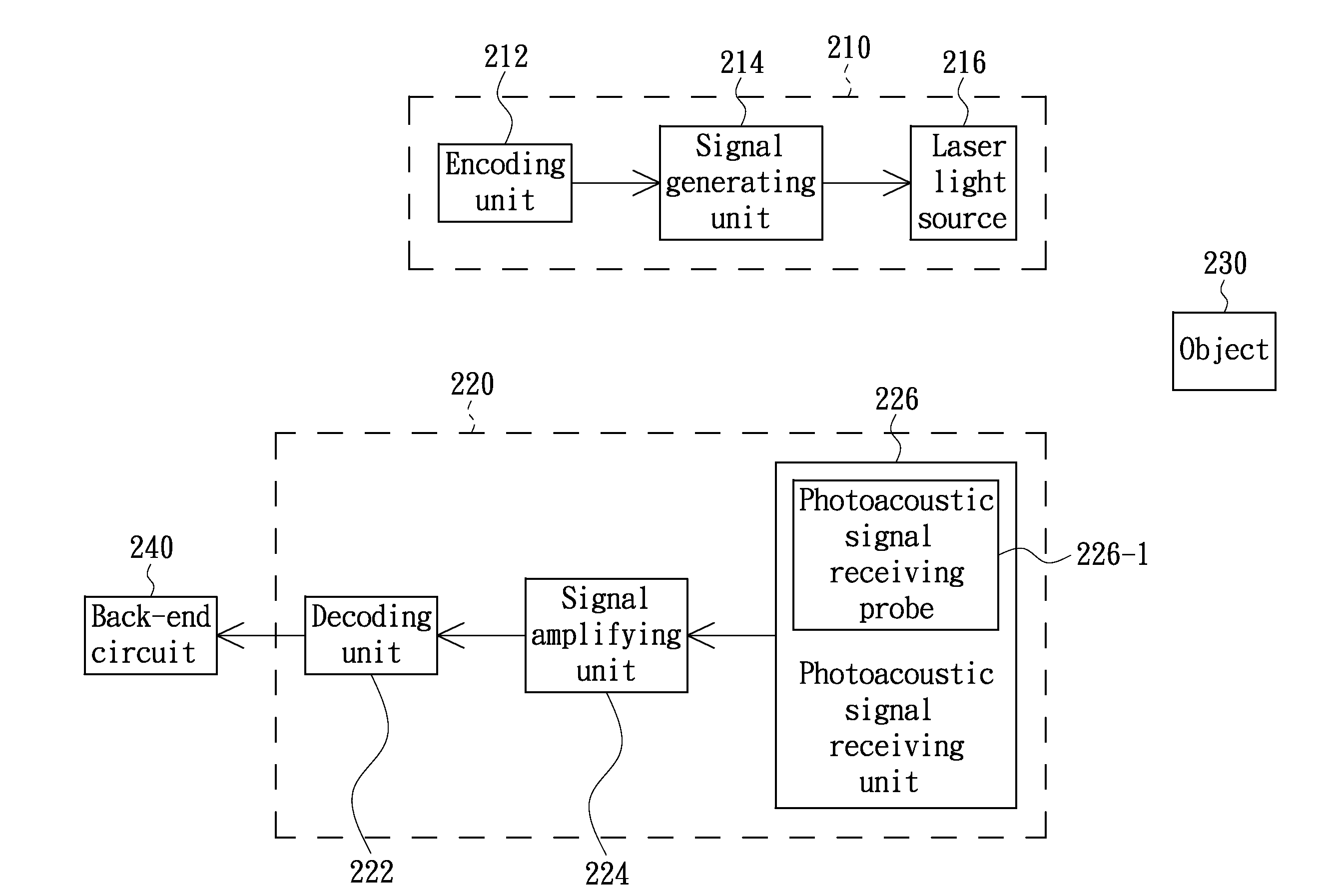
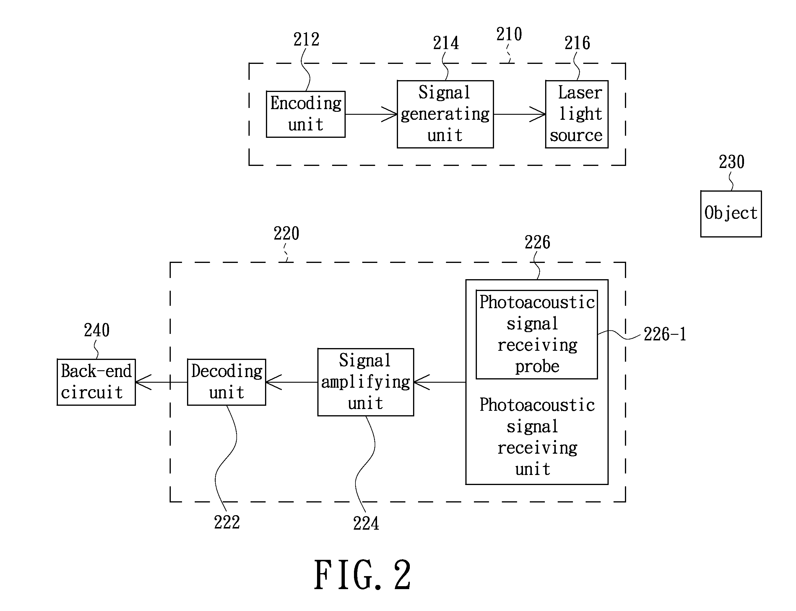
[0031]FIG. 2 shows a photoacoustic imaging system in accordance with a preferred embodiment of the present invention. Referring to FIG. 2, the photoacoustic imaging system includes a coded laser emitting apparatus 210 and a photoacoustic signal receiving apparatus 220. The coded laser emitting apparatus 210 includes an encoding unit 212, a signal generating unit 214 and a laser light source 216. The encoding unit 212 is used for generating a coded signal, and the signal generating unit 214 is used for generating a modulated signal according to the coded signal. The laser light source 216 is used for generating a laser pulse havin...


PUM


Abstract

A photoacoustic imaging system comprising a coded laser emitting apparatus and a photoacoustic signal receiving apparatus is provided. The coded laser emitting apparatus comprises an encoding unit, a signal generating unit and a laser light source. The encoding unit is used for generating a coded signal. The signal generating unit is used for generating a modulated signal according to the coded signal. The laser light source is used for generating a laser pulse having a specific coded waveform according to the modulated signal. The photoacoustic signal receiving apparatus comprises a photoacoustic signal receiving unit and a decoding unit. The photoacoustic signal receiving unit is used for receiving a photoacoustic signal generated by an object having received the laser pulse and converts the photoacoustic signal into an electrical signal. The decoding unit is used for performing a decoding operation on the aforementioned electrical signal to generate a decoding result, so that a back-end circuit can construct a photoacoustic image according to the decoding result.

Description

FIELD OF THE INVENTION[0001]The present invention generally relates to technologies in photoacoustic technology field, and more particularly to a photoacoustic imaging system, and to a coded laser emitting apparatus and a photoacoustic signal receiving apparatus of the photoacoustic imaging system.BACKGROUND OF THE INVENTION[0002]Potoacoustic technologies are classified into two types according to the laser source thereof. One type is solid laser, a common technology of which is implemented for generating a photoacoustic signal through a Q-switched Nd:YAG laser. The other type is implemented for generating a photoacoustic signal through semiconductor laser. However, both the technologies of aforementioned two types have defect. A laser pulse power of the Q-switched Nd:YAG laser can generate a photoacoustic signal, but the defect of the manner is that an imaging rate of a photoacoustic image is limited by the pulse repetition frequency of the Q-switched Nd:YAG laser. The pulse repeti...

Claims


Application Information

Patent Timeline
IPC IPC(8): G01H9/00H04B10/04
CPCH04J14/08G01N21/1702
Inventor LI, PAI-CHI
Owner LI PAI CHI
Why Eureka
Try Eureka