
Heave stabilized barge system for floatover topsides installation

Inactive Publication Date: 2012-07-05
TECH FRANCE SA
View PDF4 Cites 13 Cited by
  • Summary
  • Abstract
  • Description
  • Claims
  • Application Information

AI Technical Summary

Benefits of technology

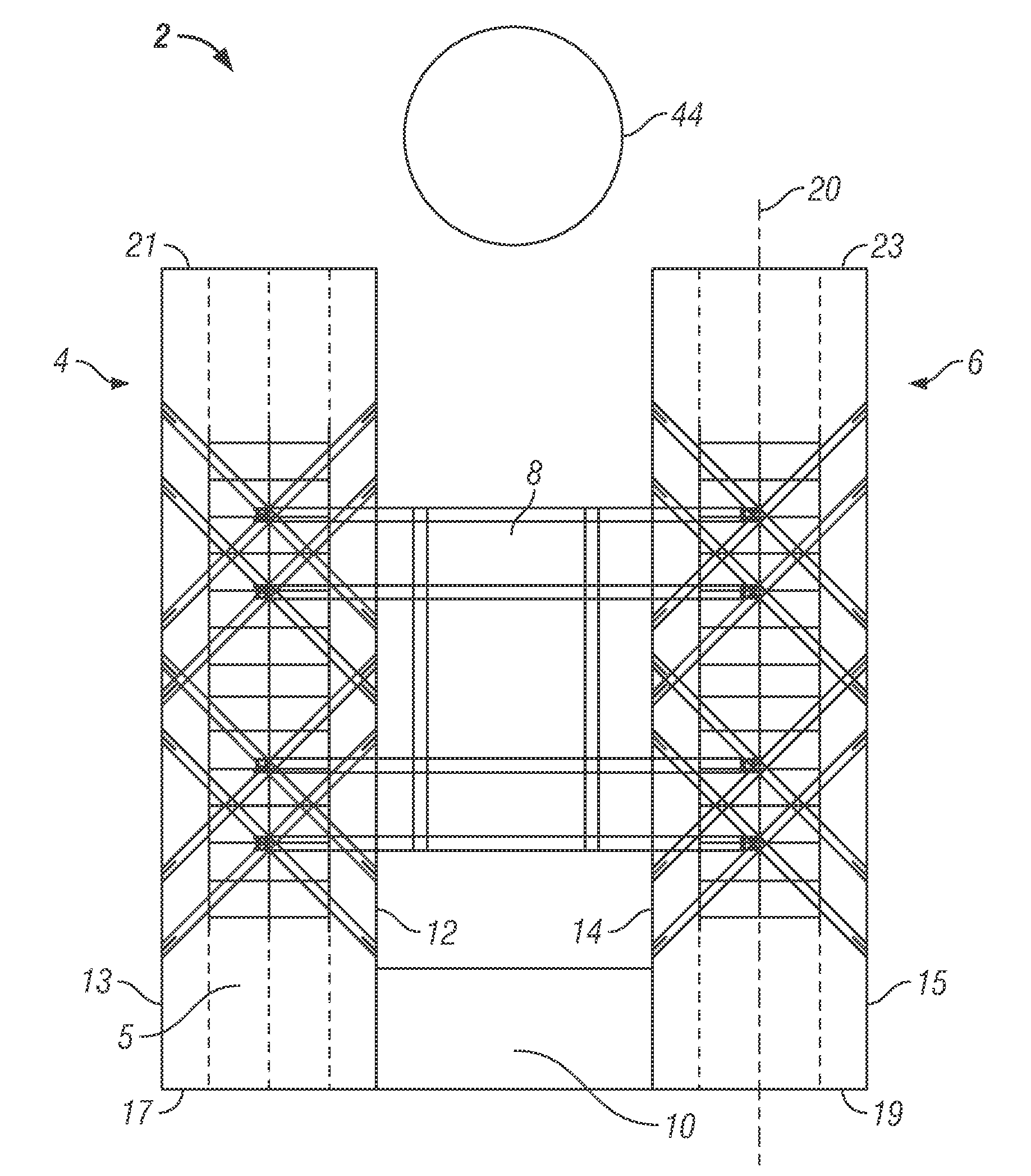
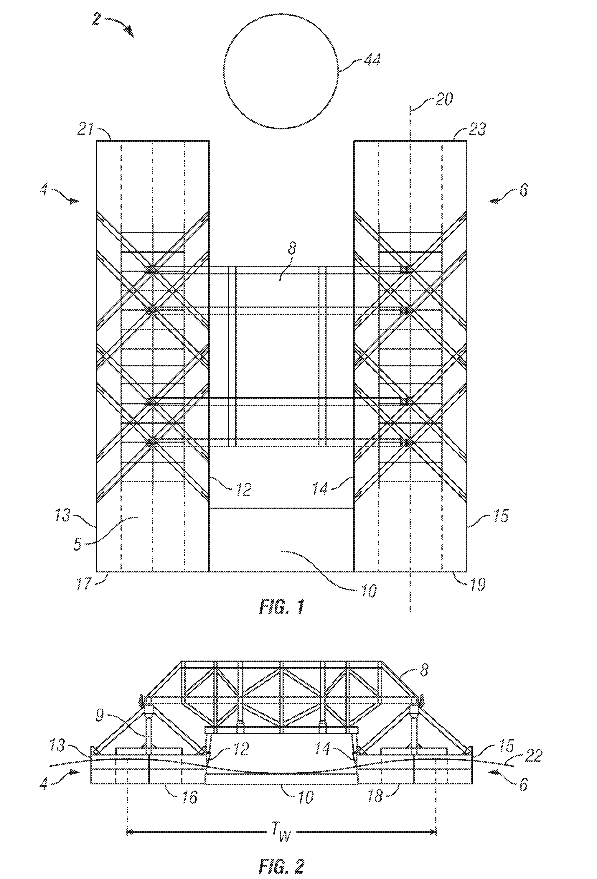
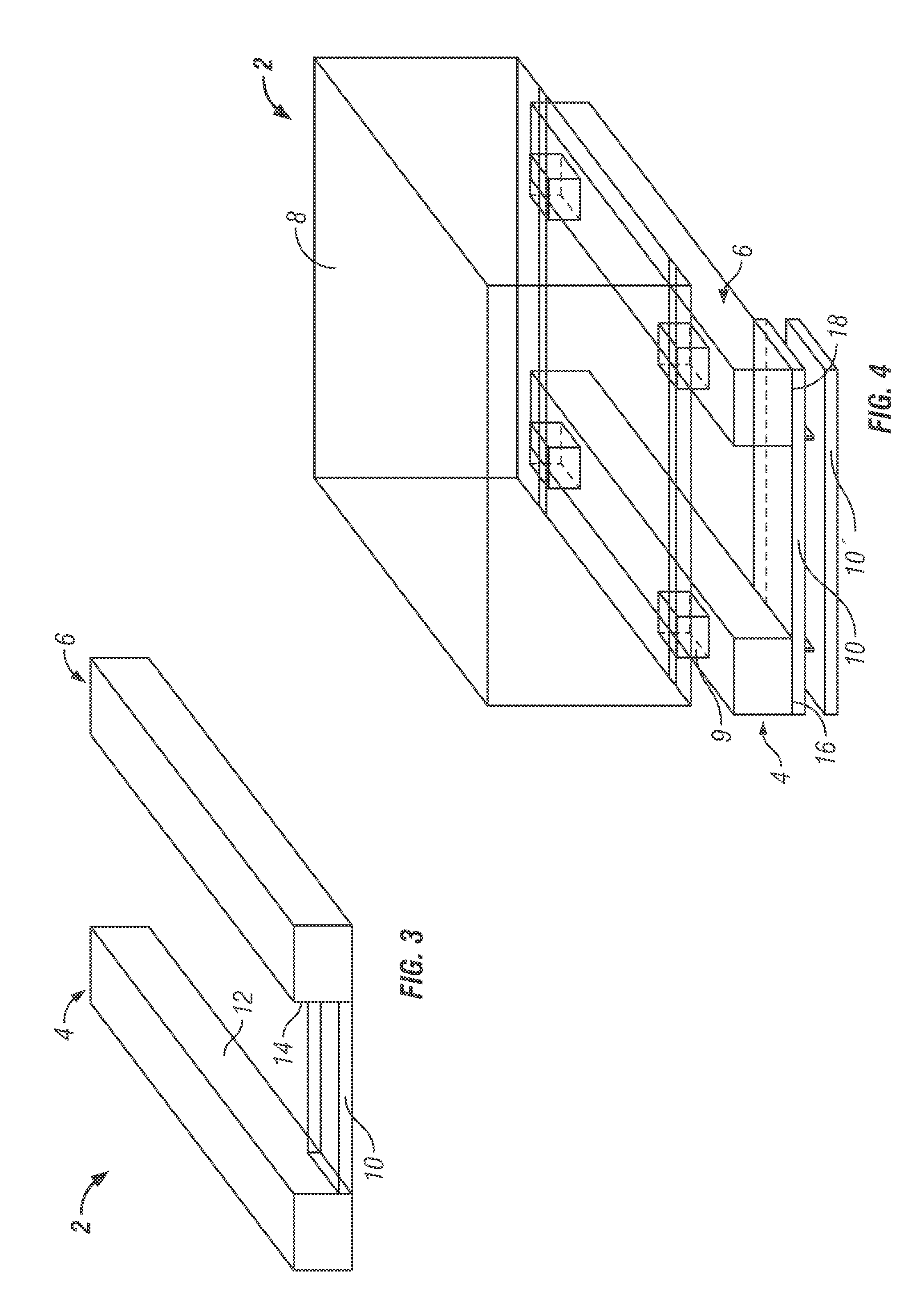
[0014]The present invention increases the heave resistance rate of a barge system from wave motion, as the system is used to install a topsides to offshore structures. One or more heave plates can be coupled at a location below the water surface to the one or more barges to change the resonance period of motion of the barge or barges relative to the period of wave motion to better stabilize the barge and resist the heave. In at least one embodiment, a heave plate can be coupled between the barges, or on an end or side of a barge. In at least another embodiment, each barge can have a heave plate and the heave plates can be releasably coupled to each other. Further, the heave plate can be rotated to an upward orientation during transportation of the topsides to the installation site to reduce drag during transportation, and then rotated to a submerged position during the installation of the topsides to the offshore structure.

Problems solved by technology

Installing a deck or topsides to an offshore floating structure has always been a challenge, particularly on deep draft floaters like the Spar, which are installed in relatively deep water.
The separation causes significant load on the barges primarily from the frequency and timing of wave motion on each barge.
Similar issues and challenges occur with single barge floatover systems.
The single barge is susceptible to similar heave and differential motion relative to the offshore structure.
With a relative stable offshore structure and a relatively unstable barge affected especially by beam seas, the transfer of the topsides to the offshore structure can be difficult.
The heave causes significant differential movement between the topsides and the offshore structure, and complexities in smoothly and efficiently installing the topsides to the offshore structure.

Method used


Image

  • Heave stabilized barge system for floatover topsides installation
  • Heave stabilized barge system for floatover topsides installation
  • Heave stabilized barge system for floatover topsides installation

Examples


Embodiment Construction

[0043]The Figures described above and the written description of specific structures and functions below are not presented to limit the scope of what Applicants have invented or the scope of the appended claims. Rather, the Figures and written description are provided to teach any person skilled in the art how to make and use the inventions for which patent protection is sought. Those skilled in the art will appreciate that not all features of a commercial embodiment of the inventions are described or shown for the sake of clarity and understanding. Persons of skill in this art will also appreciate that the development of an actual commercial embodiment incorporating aspects of the present inventions will require numerous implementation-specific decisions to achieve the developer's ultimate goal for the commercial embodiment. Such implementation-specific decisions may include, and likely are not limited to, compliance with system-related, business-related, government-related and oth...


PUM


Abstract

The present invention increases the heave resistance rate of a barge system from wave motion, as the system is used to install a topsides to offshore structures. One or more heave plates can be coupled at a location below the water surface to one or more barges to change the period of motion of the barge(s) relative to the period of wave motion to better stabilize the barge(s) and resist the heave. A heave plate can be coupled between the barges, or on end(s) or side(s) of the barge(s). In at least another embodiment, each barge can have a heave plate and the heave plates can be releasably coupled to each other. Further, the heave plate can be rotated to an upward orientation during transportation of the topsides to the installation site to reduce drag, and then rotated to a submerged position during the installation of the topsides.

Description

CROSS REFERENCE TO RELATED APPLICATIONS[0001]This application is an international application and claims the benefit of U.S. Provisional Application No. 61 / 236,935, filed Aug. 26, 2009, titled “Heave Stabilized Barge System for Floatover Topsides Installation.”STATEMENT REGARDING FEDERALLY SPONSORED RESEARCH OR DEVELOPMENT[0002]Not applicable.REFERENCE TO APPENDIX[0003]Not applicable.BACKGROUND OF THE INVENTION[0004]1. Field of the Invention[0005]The invention disclosed and taught herein relates generally to floating barges used to install a topsides for offshore structures; and more specifically related to systems and methods for stabilizing heave caused by wave action on a barge system during the installation of the topsides.[0006]2. Description of the Related Art[0007]A Spar platform is a type of floating oil platform typically used in very deep waters and is among the largest offshore structures in use. A Spar platform includes a large cylinder or hull supporting a typical rig t...

Claims


Application Information

Patent Timeline
IPC IPC(8): B63B39/06B63B35/00
CPCB63B9/065B63B2039/067B63B39/06B63B35/003B63B75/00
Inventor LAMBRAKOS, KOSTAS FILOKTITISKOO, BONJUNO'SULLIVAN, JAMES
Owner TECH FRANCE SA
Learn More