
Lightweight reinforced conveyor belt structure

a technology of reinforced conveyor belts and heavy-duty steel, which is applied in the direction of conveyors, transportation and packaging, etc., can solve problems such as operating efficiency, and achieve the effects of high tenacity, light weight and high strength

Inactive Publication Date: 2012-07-05
ADVANCED COMPOSITE STRUCTURES LTD
View PDF1 Cites 20 Cited by
  • Summary
  • Abstract
  • Description
  • Claims
  • Application Information

AI Technical Summary

Benefits of technology

[0005]In accordance with this invention, there is provided a conveyor belt structure comprising a reinforcing fabric base layer, the fabric base comprising a network of high tenacity fibers, and an outer or surface layer of rubber, the basic fabric layer and the outer surface layer being bonded together. The result is a stronger belt that is lighter than other reinforced belt structures. Because of the strength and lightness of weight in the reinforcing base layer, the amount of rubber can be reduced, so that the resulting belt is stronger and lighter and therefore takes less energy to operate. For certain applications, the rubber layer may be bonded to both sides of the fabric base layer.
[0007]The present invention provides a lightweight, but strong conveyor belt structure that is formed from a composite material. The composite material includes a high tenacity fiber containing reinforcing layer and an abrasion resistant rubber surface layer. The composite material for the conveyor belts of this invention is engineered to provide a variety of properties, such as lightness of weight, higher strength, abrasion resistance and / or chemical resistance. Specific properties are dependent on the type of fiber and rubber selected for the specific end use. The lightness of weight without sacrifice of strength leads to operating efficiencies. Preferably the belt is flexible.

Problems solved by technology

The lightness of weight without sacrifice of strength leads to operating efficiencies.

Method used


Image

  • Lightweight reinforced conveyor belt structure
  • Lightweight reinforced conveyor belt structure
  • Lightweight reinforced conveyor belt structure

Examples


example 1

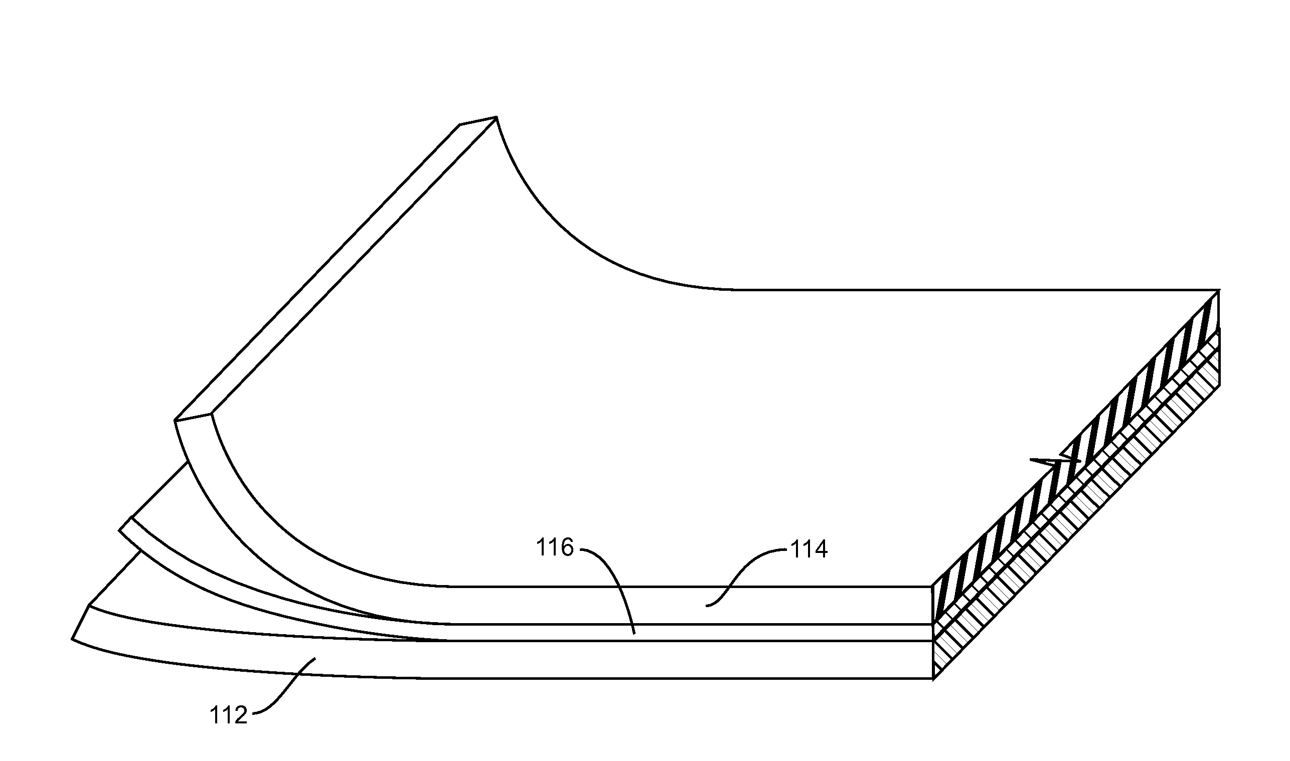
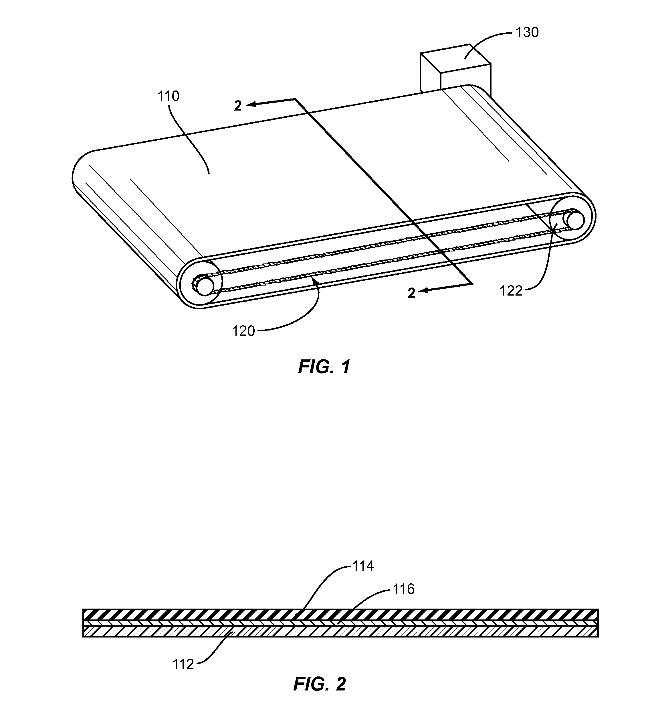
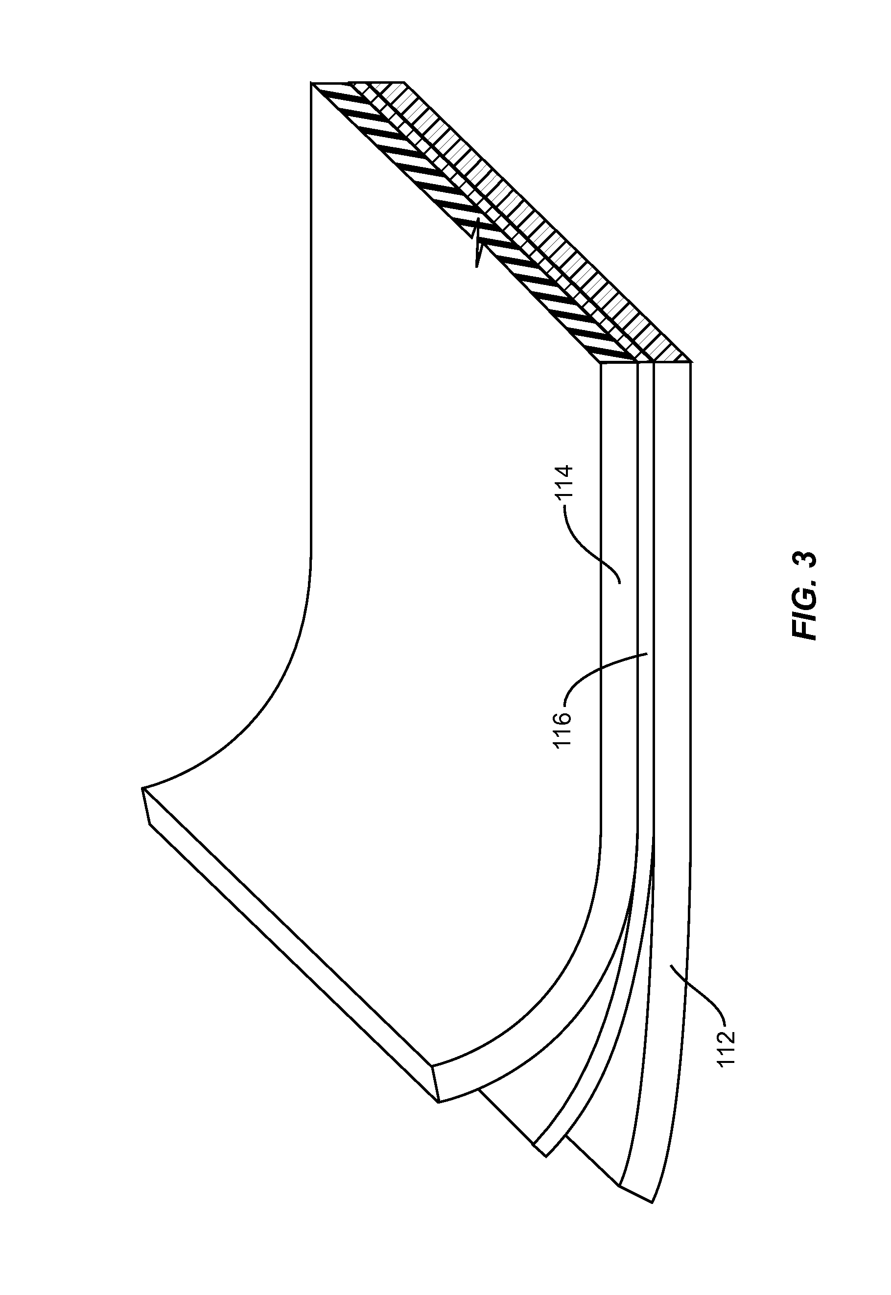
[0054]A reinforcing fabric was formed from a woven fabric (style 902 from Hexcel) of 1200 denier ultra high molecular weight polyethylene yarn, designated SPECTRA® 900 from Honeywell International Inc., having tensile properties of 28 g / d tenacity and 775 g / d modulus. The fabric was a 17×17 ends / inch (6.7×6.7 ends / cm) plain weave fabric having a thickness of 0.017 inch (0.43 mm).

[0055]A bonding layer film formed from an ethylene vinyl acetate polymer (EVA) film having a thickness of 0.003 inch (0.076 mm) was tacked to one side of the fabric. The rubber compound layer was formed from a blend of 80% natural rubber and 20% of styrene butadiene (formulation 2148 from Specialty Tires) and was attached to the bonding layer. The thickness of the rubber layer is 0.0625 inch (1.6 mm).

[0056]Lengths of fabric / EVA / rubber were laid out and formed into a roll. The tightly wound roll was wrapped with heat resistant tape and heated in an oven to a temperature of between 210° F. and 300° F. for up t...

example 2

[0058]Example 1 is repeated using as the fibrous layer Kevlar® 29 fabric from Du Pont.

[0059]Similar results are noted.

example 3

[0060]Example 1 is repeated using as the fabric layer a unidirectionally oriented structure of high modulus polyethylene fibers.

[0061]Similar results are noted.


PUM


Abstract

Conveyor belts formed of a composite fabric structure. The fabric structure has a base reinforcing layer made of a network that includes high tenacity fibers. The composite fabric structure also includes a surface layer formed of rubber. The base layer and the surface layer are bonded together, preferably through the use of a bonding layer.

Description

BACKGROUND OF THE INVENTION[0001]1. Field of the Invention[0002]This invention relates to conveyor belt structures which are light in weigh, but have high strength.[0003]2. Description of the Related Art[0004]Many types of conveyor belts are subject to extreme wear leading to rupture or other forms of failure. For example, conveyor belts used in mining operations fail frequently, which can cause an expensive shutdown for several hours. Other conveyor belts lack the strength to be used in extreme conditions. Reinforcing such types of conveyor belts is known, but generally involves the use of reinforcing materials that add to the weight which increases the energy necessary to drive the belt.SUMMARY OF THE INVENTION[0005]In accordance with this invention, there is provided a conveyor belt structure comprising a reinforcing fabric base layer, the fabric base comprising a network of high tenacity fibers, and an outer or surface layer of rubber, the basic fabric layer and the outer surfac...

Claims


Application Information

Patent Timeline
Patent Type & Authority Applications(United States)
IPC IPC(8): B65G15/34B65G15/28
CPCB65G15/34
Inventor HOLLAND, JOHN E.HOLLAND, CONNIE W.NATHAN, DANIEL M.NGUYEN, HUY X.PARRISH, ELIZABETH S.
Owner ADVANCED COMPOSITE STRUCTURES LTD
Learn More