Current Share Configuration in a Power Converter System

a current share and power converter technology, applied in the direction of electric variable regulation, process and machine control, instruments, etc., can solve the problem that the potential of pmbus signalling to provide significant efficiency gains in such current sharing schemes has gone unrecognised, and achieve the effect of reducing processing operations and minimising hardware and processing requirements

Active Publication Date: 2012-07-05
TELEFON AB LM ERICSSON (PUBL)
View PDF4 Cites 17 Cited by
  • Summary
  • Abstract
  • Description
  • Claims
  • Application Information

AI Technical Summary

Benefits of technology

[0010]Moreover, the present inventors have devised a particularly efficient scheme for designating a voltage converting module as the master and each other voltage converting module as a slave, so that no additional hardware of significant additional processing is required to establish a master-slave configuration. In particular, the present inventors have found that the establishment of a master-slave configuration can be implemented particularly efficiently by using PMBus signalling to establish a master-slave (or “primary-secondary”) relationship between the voltage converting modules, as will become clear from the following.
[0012]Accordingly, not only does an embodiment of the present invention reduce the processing operations performed by voltage converting modules to exchange current sharing information by providing a master-slave relationship between the voltage converting modules, but the embodiment also minimises the hardware and processing requirements needed to set up the master-slave relationship.

Problems solved by technology

However, although PMBus and proprietary communication protocols have been widely used in power system communications in recent years, and have been implemented in power systems alongside current-sharing schemes of the kind described above, the potential of PMBus signalling to provide significant efficiency gains in such current sharing schemes has heretofore gone unrecognised.

Method used


Image

  • Current Share Configuration in a Power Converter System
  • Current Share Configuration in a Power Converter System
  • Current Share Configuration in a Power Converter System

Examples


Embodiment Construction

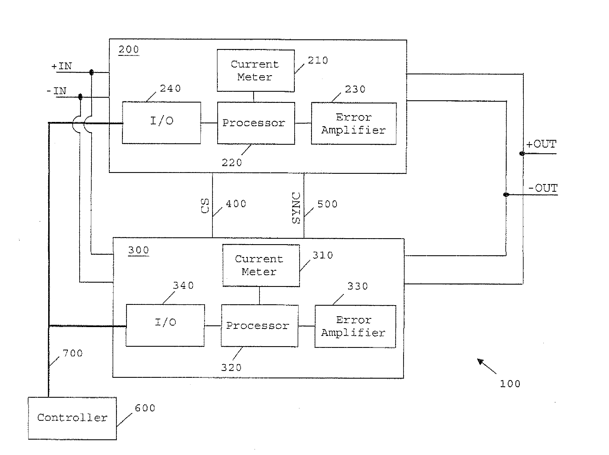
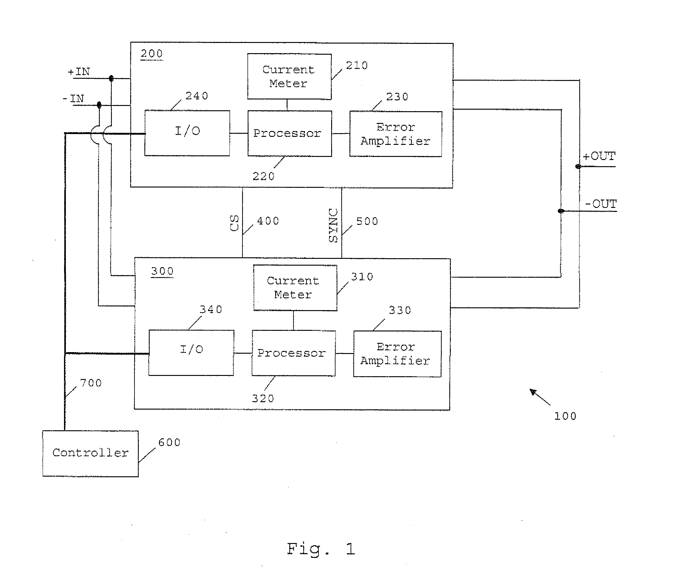
[0027]FIG. 1 is a schematic of a power converter system 100 according to an embodiment of the present invention. The system 100 includes a first voltage converting module in the form of a DC / DC converter 200, and a second voltage converting module 300 which is also a DC / DC converter. In the present embodiment the voltage converting modules 200 and 300 are switched mode power supplies (SMPS) which are preferably set to operate at substantially equal switching frequencies. Voltage converting modules 200 and 300 are connected together in parallel as shown in FIG. 1, with their corresponding input voltage terminals being connected to power input lines +IN and −IN. The voltage converting modules 200 and 300 are thus parallel-coupled to provide a current to a common load (not shown). Most preferably, the modules are Ericsson BMR 453 Series DC / DC converters. Where such converters are used to implement a power converter system according to the invention, Pins 1 and 4 of each converter shoul...


PUM


Abstract

A power converter system is provided, which comprises a first voltage converting module for converting an input voltage to an output voltage, and a second voltage converting module for converting the input voltage to an output voltage, the second voltage converting module being connected in parallel with the first: voltage converting module. The power converter sys tem also includes at least one signalling line between the first voltage converting module and the second voltage converting module, and a current share controller operatively connected to communicate with the first and second voltage converting modules using the Power Management Bus protocol to establish a master- slave relationship between the first and second voltage converting modules, comprising a master voltage converting module and a slave voltage converting module. The first and second voltage converting modules are arranged to operate in a current share configuration so as to share a load current of the power converter system. The master voltage converting module is arranged to determine its output current and send a signal indicative of its output current to the slave voltage converting module via the at least one signalling line. The slave voltage converting module is arranged to adjust its output current in dependence upon the signal from the master voltage converting module.

Description

TECHNICAL FIELD[0001]The present invention generally relates to the field of power converter systems having parallel-coupled voltage converting modules, and more specifically to methods of configuring and controlling the sharing of the power system's load current between the voltage converting modules.BACKGROUND[0002]In many power applications parallel coupling of voltage converting modules (also widely referred to as voltage converters, power supplies or power modules), such as point-of-load (POL) converters, isolated DC / DC converters, bus converters or AC / DC power supplies, caters for the increasing need for greater total power. For example, a typical DC / DC system has an intermediate voltage level of 48 VDC, which is converted down to a typical level of 9-12 VDC. Since this 9-12 V DC-level often requires DC / DC converters that can handle high output current it is often desirable to couple two or more converters in parallel to provide a power converter system in which the load curre...

Claims


Application Information

Patent Timeline
Patent Type & Authority Applications(United States)
IPC IPC(8): G05F1/46
CPCH02J1/102H02M7/493H02J3/46
Inventor MALMBERG, JONASAPPELBERG, MIKAELKULLMAN, ANDERS
Owner TELEFON AB LM ERICSSON (PUBL)
Why Eureka
Try Eureka