Motion monitoring system for monitoring motion within a region of interest

a motion monitoring and motion technology, applied in the field of motion monitoring systems, can solve the problems of time-consuming and uncomfortable for patients, and achieve the effect of reducing motion artifacts

Inactive Publication Date: 2012-07-05
KONINKLIJKE PHILIPS ELECTRONICS NV
View PDF2 Cites 20 Cited by
  • Summary
  • Abstract
  • Description
  • Claims
  • Application Information

AI Technical Summary

Benefits of technology

[0004]It is an object of the present invention to provide a motion monitoring system, method and computer program for monitoring motion within a region of interest, which is allows detecting motion within a region of interest without contacting an object to be imaged, wherein the detected motion can be used for reducing motion artifacts in an image of the region of interest. It is a further object of the present invention to provide a corresponding imaging system, imaging method and imaging computer program for imaging the region of interest.

Problems solved by technology

This providing and removing of electrodes is time consuming and can be uncomfortable for a patient.

Method used


Image

  • Motion monitoring system for monitoring motion within a region of interest
  • Motion monitoring system for monitoring motion within a region of interest
  • Motion monitoring system for monitoring motion within a region of interest

Examples


Embodiment Construction

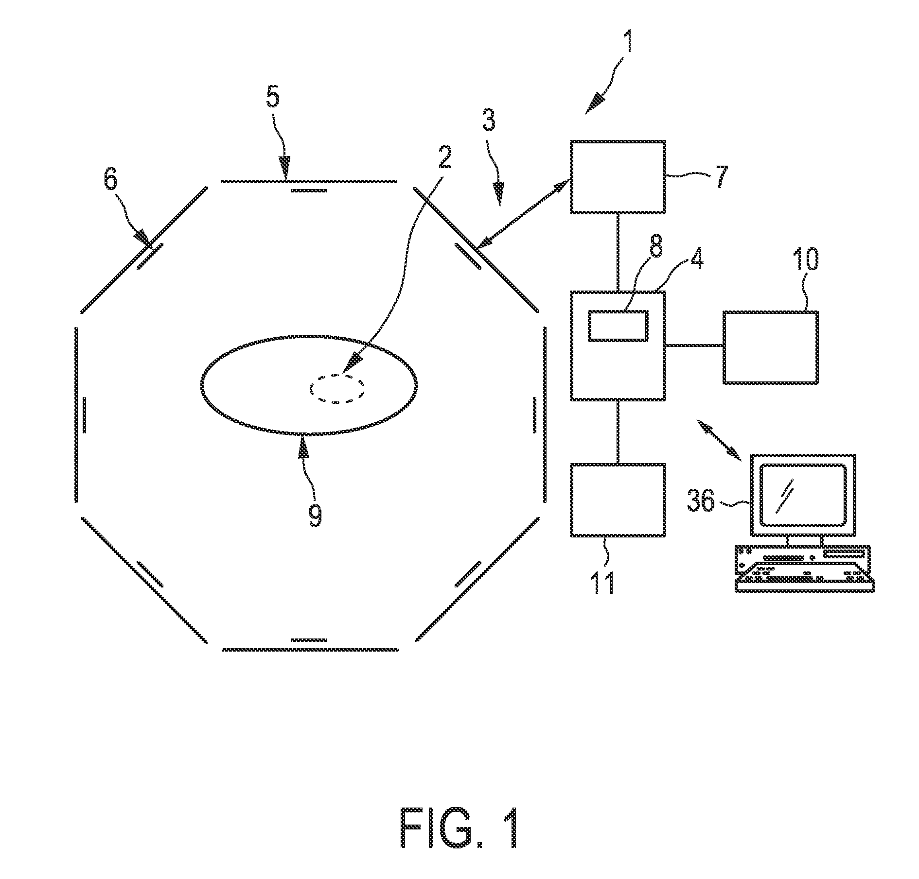
[0058]FIG. 1 shows schematically and exemplarily an embodiment of a motion monitoring system 1 for monitoring motion within a region of interest 2. The motion monitoring system 1 comprises a MIT detection data acquisition unit 3 for acquiring MIT detection data of the region of interest 2 and a motion determining unit 4 for determining motion within the region of interest 2 based on the acquired MIT detection data.

[0059]MIT detection data acquisition unit 3 comprises MIT transmitting coils 5 for applying alternating magnetic fields to the region of interest 2 and MIT receiving coils 6 for receiving MIT signals from the region of interest 2 by measuring voltage changes in the receiving coils 6 induced by field perturbations in the region of interest 2. The MIT transmitting coils 5 and the MIT receiving coils 6 are controlled by a MIT detection data generation unit 7 which generates MIT detection data based on the voltage changes in the MIT receiving coils 6.

[0060]The MIT transmitting...


PUM


Abstract

The invention relates to a motion monitoring system (1) for monitoring motion within a region of interest (2). The motion monitoring system (1) comprises a magnetic induction tomography detection data acquisition unit (3) for acquiring MIT detection data of the region of interest (2), and a motion determining unit (4) for determining motion within the region of interest (2) based on the acquired MIT detection data. The invention relates further to an imaging system for imaging a region of interest comprising the motion monitoring system (1). The determined motion can be used for reducing motion artifacts in reconstructed images.

Description

FIELD OF THE INVENTION[0001]The invention relates to a motion monitoring system, method and computer program for monitoring motion within a region of interest. The invention relates further to an imaging system, an imaging method and an imaging computer program for imaging the region of interest.BACKGROUND OF THE INVENTION[0002]The article “Motion in cardiovascular MR imaging”, Scott A. D., Keegan J., Firmin D. N., Radiology. 2009 February, 250(2):331-51 discloses a magnetic resonance (MR) imaging system for generating a MR image of the human heart. MR detection data are acquired, and in parallel an electrocardiogram is measured for determining different cardiac phases. The MR image is reconstructed using MR detection data which have been acquired while the heart is in the same cardiac phase. This consideration of the cardiac phase while reconstructing the MR image reduces motion artifacts in the reconstructed MR image.[0003]Before the acquisition of the MR detection data the patien...

Claims


Application Information

Patent Timeline
Patent Type & Authority Applications(United States)
IPC IPC(8): G01R33/025
CPCG06T7/2033G06T2207/30048G06T2207/10072G06T7/246
Inventor KATSCHER, ULRICHBOERNERT, PETERSTEHNING, CHRISTIANGRAESSLIN, INGMAR
Owner KONINKLIJKE PHILIPS ELECTRONICS NV
Why Eureka
Try Eureka