External light glare assessment device, line of sight detection device and external light glare assessment method

a technology of external light glare and assessment method, which is applied in the direction of acquiring/recognising eyes, instruments, image enhancement, etc., can solve the problem of difficult to estimate the reflection state highly accurately from indirect information other than reflection itsel

Active Publication Date: 2012-07-05
PANASONIC INTELLECTUAL PROPERTY CORP OF AMERICA
View PDF7 Cites 20 Cited by
  • Summary
  • Abstract
  • Description
  • Claims
  • Application Information

AI Technical Summary

Benefits of technology

[0016]With the present invention, it is possible to provide an ambient light reflection determination apparatus, a line-of-sight detection apparatus, and an ambient light re

Problems solved by technology

Thus, it is difficult to estimate a reflection state highly acc

Method used


Image

  • External light glare assessment device, line of sight detection device and external light glare assessment method
  • External light glare assessment device, line of sight detection device and external light glare assessment method
  • External light glare assessment device, line of sight detection device and external light glare assessment method

Examples


embodiment 1

[0026][Configuration of Reflection Determination Apparatus 100]

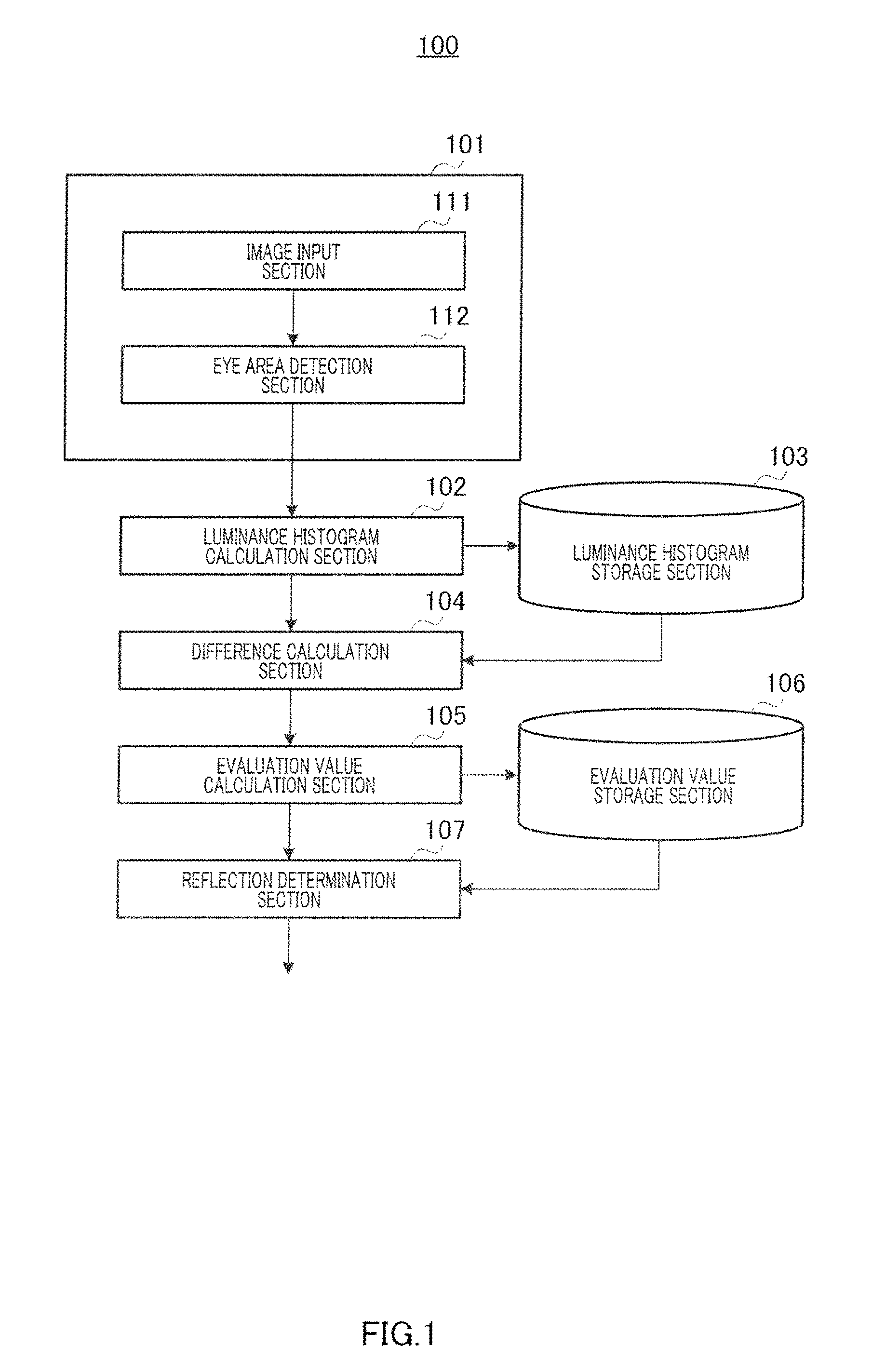
[0027]FIG. 1 is a block diagram showing a configuration of reflection determination apparatus 100 according to Embodiment 1 of the present invention.

[0028]Reflection determination apparatus 100 determines whether or not the extent of a reflection phenomenon caused by reflection of ambient light to eyeglasses exceeds a predetermined level. Reflection determination apparatus 100 is installed, e.g., in a cabin of an automobile and is connected to a line-of-sight detection apparatus in use. This line-of-sight detection apparatus executes processing of detecting a line-of-sight direction of a driver only in a case where reflection determination apparatus 100 determines reflection is weak. Hereinafter, in particular, a case where reflection determination apparatus 100 is applied to the line-of-sight detection apparatus will be described.

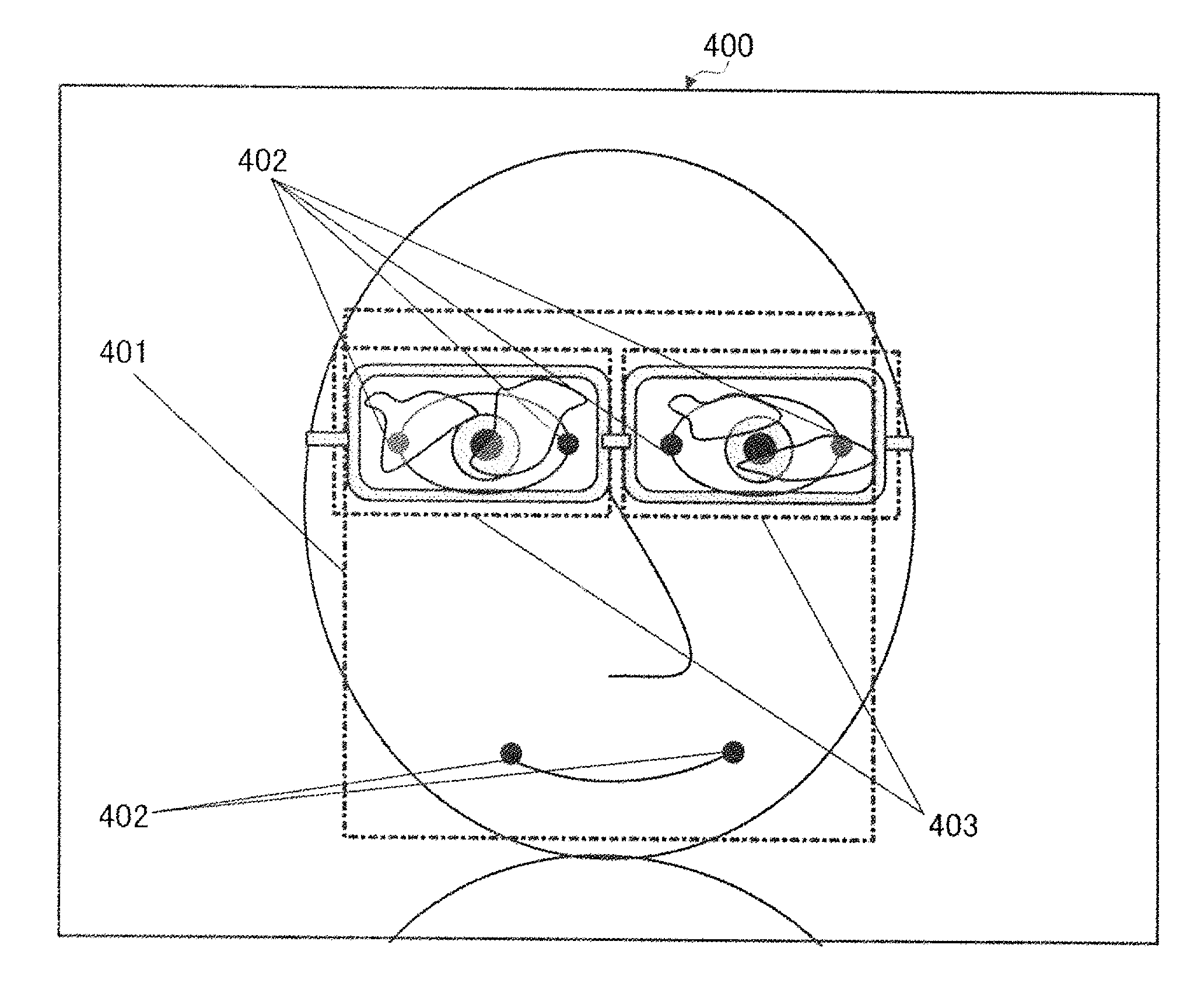
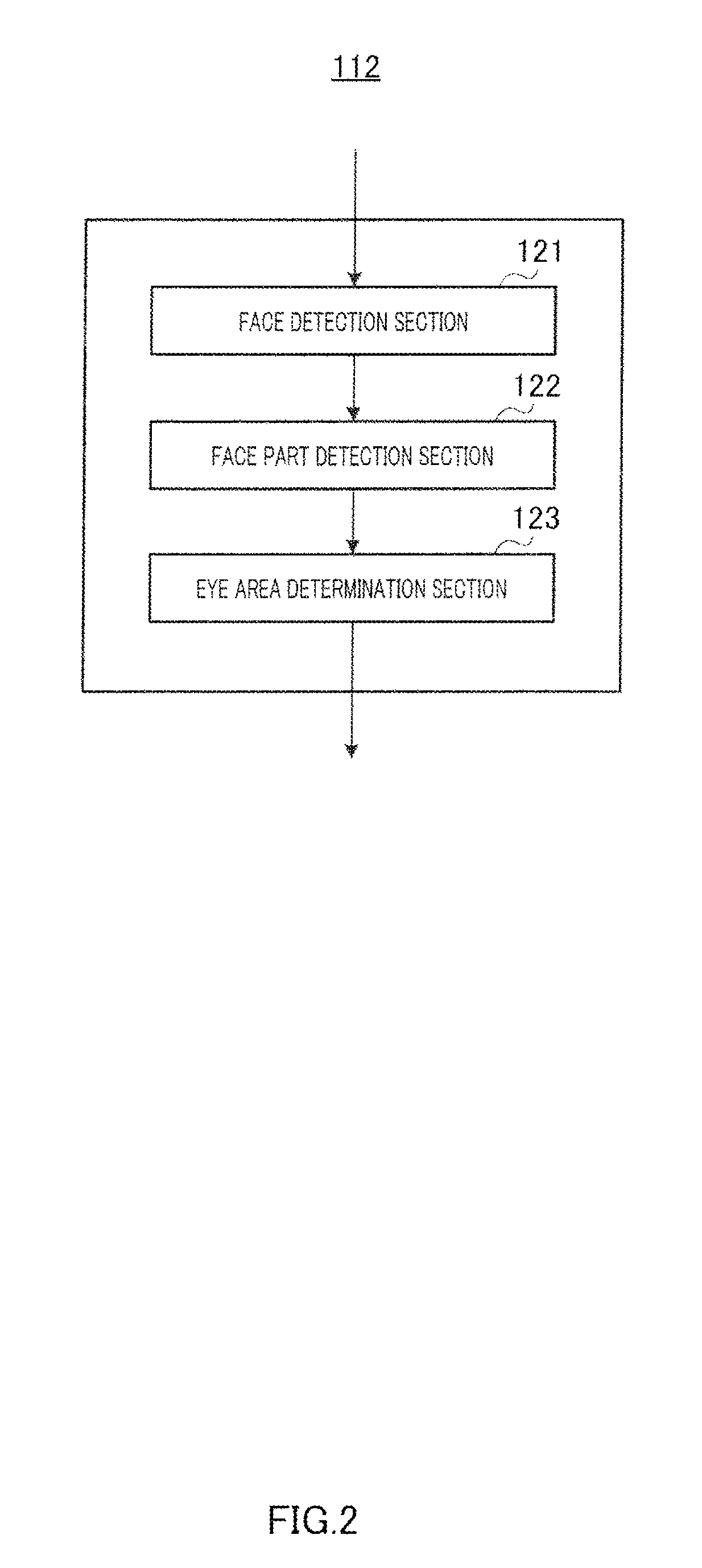
[0029]In FIG. 1, reflection determination apparatus 100 includes eye area image acquisition...

embodiment 2

[0092]Embodiment 2 relates to a reflection determination apparatus calculating an evaluation value in a similar manner to reflection determination apparatus 100 according to Embodiment 1 and calculating credibility of a pupil detection result or the like based on the calculated evaluation value. In the description of Embodiment 1, pupil detection is not performed in a case where the evaluation value exceeds a predetermined value consecutively. However, even in a case where pupil detection is unstable, there is a case where a pupil detection result is desired as well as information that the detection result has low credibility. To this end, Embodiment 2 provides a pupil detection result as well as credibility information on the pupil detection result or the like.

[0093]FIG. 8 shows a configuration of reflection determination apparatus 800 according to Embodiment 2 of the present invention. In FIG. 8, components having equal functions to those in reflection determination apparatus 100 ...


PUM


Abstract

Disclosed are an ambient light reflection determination apparatus and an ambient light reflection determination method enabling to determine reflection without using an edge and even in a case where luminance of a reflection generating part in eyeglasses is low. In a reflection determination apparatus (100), a luminance histogram calculation section (102) calculates a luminance histogram representing a luminance distribution of an eye area image, a difference calculation section (104) calculates a difference histogram by finding a difference between the two luminance histograms calculated from the two eye area images having different photographing timings, an evaluation value calculation section (105) calculates an evaluation value regarding reflection of ambient light based on the difference histogram and a weight in accordance with luminance, and a reflection determination section (107) determines the reflection of ambient light based on the calculated evaluation value.

Description

TECHNICAL FIELD[0001]The present invention relates to an apparatus for determining reflection of ambient light to eyeglasses, a line-of-sight detection apparatus, and an ambient light reflection determination method.BACKGROUND ART[0002]In line-of-sight detection or facial expression detection, pupil detection is performed. When this pupil detection is performed at the time of wearing of eyeglasses, a pupil may not be detected. This is caused by a reflection phenomenon, in which ambient light is reflected to lenses of the eyeglasses. The extent of reflection of ambient light to the lenses of the eyeglasses differs depending on the material of the lenses, coating, posture of the face, intensity of the ambient light, wavelength, etc. Thus, it is difficult to estimate a reflection state highly accurately from indirect information other than reflection itself.[0003]To deal with such a problem, a method for detecting reflection of ambient light to lenses of eyeglasses (first ambient light...

Claims


Application Information

Patent Timeline
IPC IPC(8): G01N21/55
CPCG06T1/00G06T7/00G06T7/0081G06K9/0061G06T2207/30201G06T2207/30268G06T2207/10016G06T7/11G06V40/193
Inventor TSUKIZAWA, SOTAROOKA, KENJI
Owner PANASONIC INTELLECTUAL PROPERTY CORP OF AMERICA
Why Eureka
Try Eureka