Enterprise fuel managment system

a fuel management system and enterprise technology, applied in the direction of instruments, data processing applications, structural/machine measurement, etc., can solve the problems of significant unreliability, substantial complexity and difficulties, and become problemati

Active Publication Date: 2012-07-05
QT TECH
View PDF2 Cites 16 Cited by
  • Summary
  • Abstract
  • Description
  • Claims
  • Application Information

AI Technical Summary

Benefits of technology

[0010]By contrast, the present invention completely eliminates the need for local fuel management servers at each location. Instead, hand-held devices at each location forward their collected data to a data center in a central location. The central data center then forwards the aggregated data to the fleet operator's data center as data messages (for example, as MQ messages). The fleet operator's computer systems then use the data, take action in response to the data, forward messages to the pilot through the ACARS system utilizing the data, etc. In this regard, the central data center is more like a data forwarding station, sorting out the various incoming raw data received from the various hand-held units and managing the communication to the airline data center (acting like a traffic cop, of sorts). Importantly, in this arrangement, there is only one database (the fleet operator's), so there is no synchronization needed.
[0011]This enterprise approach, rather than a decentralized approach known in the prior art, has important advantages. First of all, it allows the enterprise to better control its own data. Secondly, the enterprise is more in control of all refueling decisions. Moreover, as will be described further below, the system is more amenable to large scale operations and is inherently more reliable at larger scales.
[0012]Since there is no synchronization of multiple databases and greatly simplified communication with the airline's system, system crashes due to data discrepancies / communication conflicts are eliminated or minimized. This results in substantially improved reliability. Inasmuch as downtime can ground planes and passengers, this improved reliability is a key benefit / feature of the invention.
[0013]Defined another way, the present invention comprises an enterprise fuel management system for managing fueling operations of an aircraft fleet operated by a fleet operator having a central computer system at a data center and operating aircraft at multiple airports. The system includes a central data center in communication with the fleet operator's central computer system for forwarding data to the fleet operator's central computer system. The system also includes, at each airport, one or more data collection units for collecting fueling information and forwarding it to the central data center. Advantageously, the data collection units communicate the collected fueling information wirelessly to the central data center, and the data collection units are not in direct communication with the fleet operator's central computer system. Moreover, the central data center gathers fueling information from the various data collection units and communicates the gathered fueling information to the fleet operator's central computer system as data messages for subsequent processing and action. This approach greatly smoothes out the communication from the data collection units by having them communicate with the central data center, not the fleet operator's central computer system. In this way, the fleet operator's central computer system can maintain the only database of fueling information and flight information, obviating the (prior art's) need to synchronize the data in the fleet operator's computer system with data in some other computer system. Avoiding this troublesome synchronization greatly improves data integrity, communications, and up-time.

Problems solved by technology

An unfortunate side effect of using a local server in this way is that it requires a separate server for each airport.
But it becomes problematic if a large number of airports are involved.
In practice there can be hundreds of airports for a given fleet operator (like an airline), leading to substantial complexity and difficulties.
This local server arrangement leads to significant unreliability.
As the number of airports being serviced by such a system grows for a single airline operating such a system, the number of synchronizations going on begins to become unwieldy, leading to frequent downtime as data discrepancies between the databases and / or communication conflicts bring one or more systems off-line.
Such an implementation can lead to a substantial reliability issue for the airline.

Method used


Image

  • Enterprise fuel managment system
  • Enterprise fuel managment system
  • Enterprise fuel managment system

Examples


Embodiment Construction

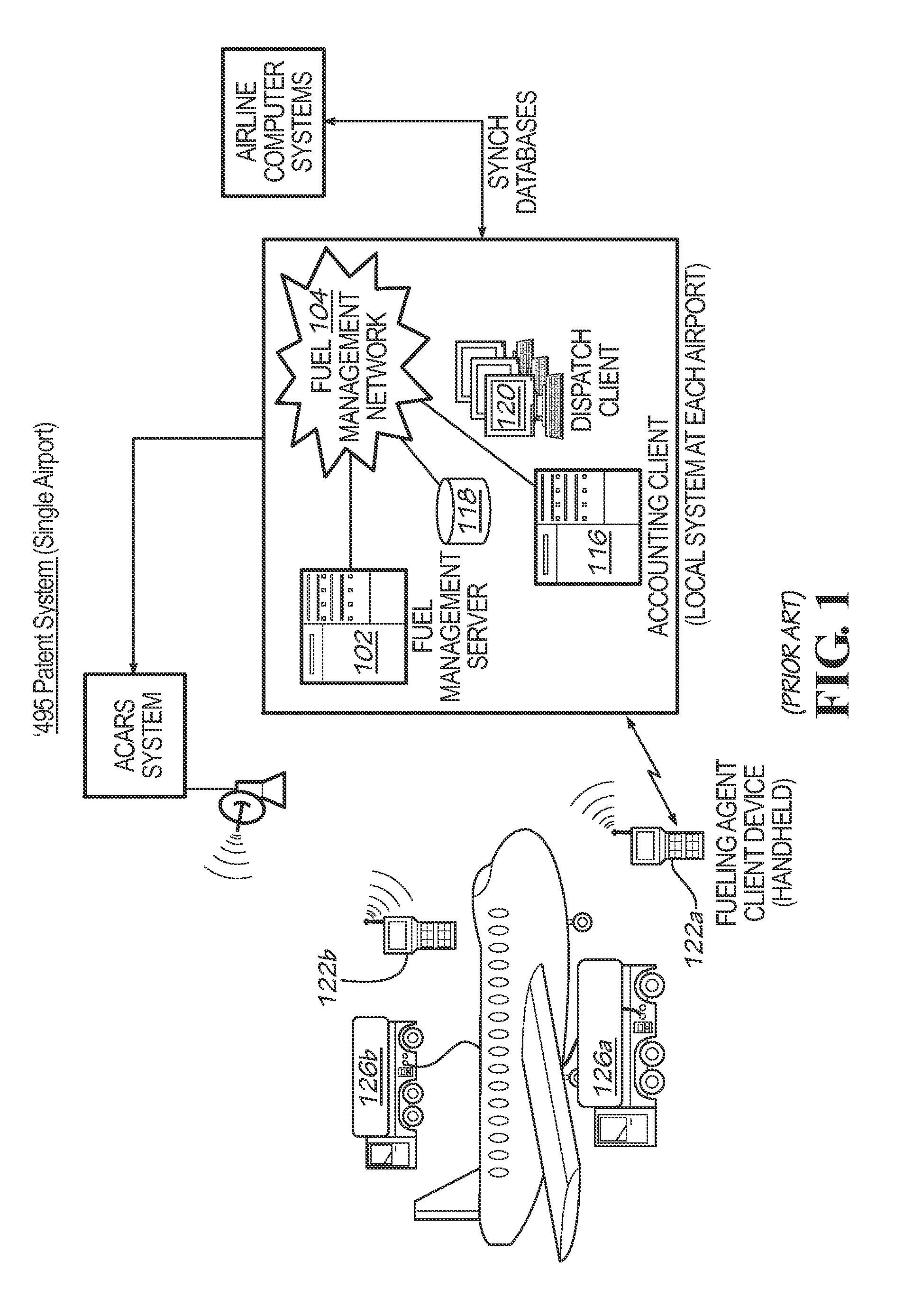
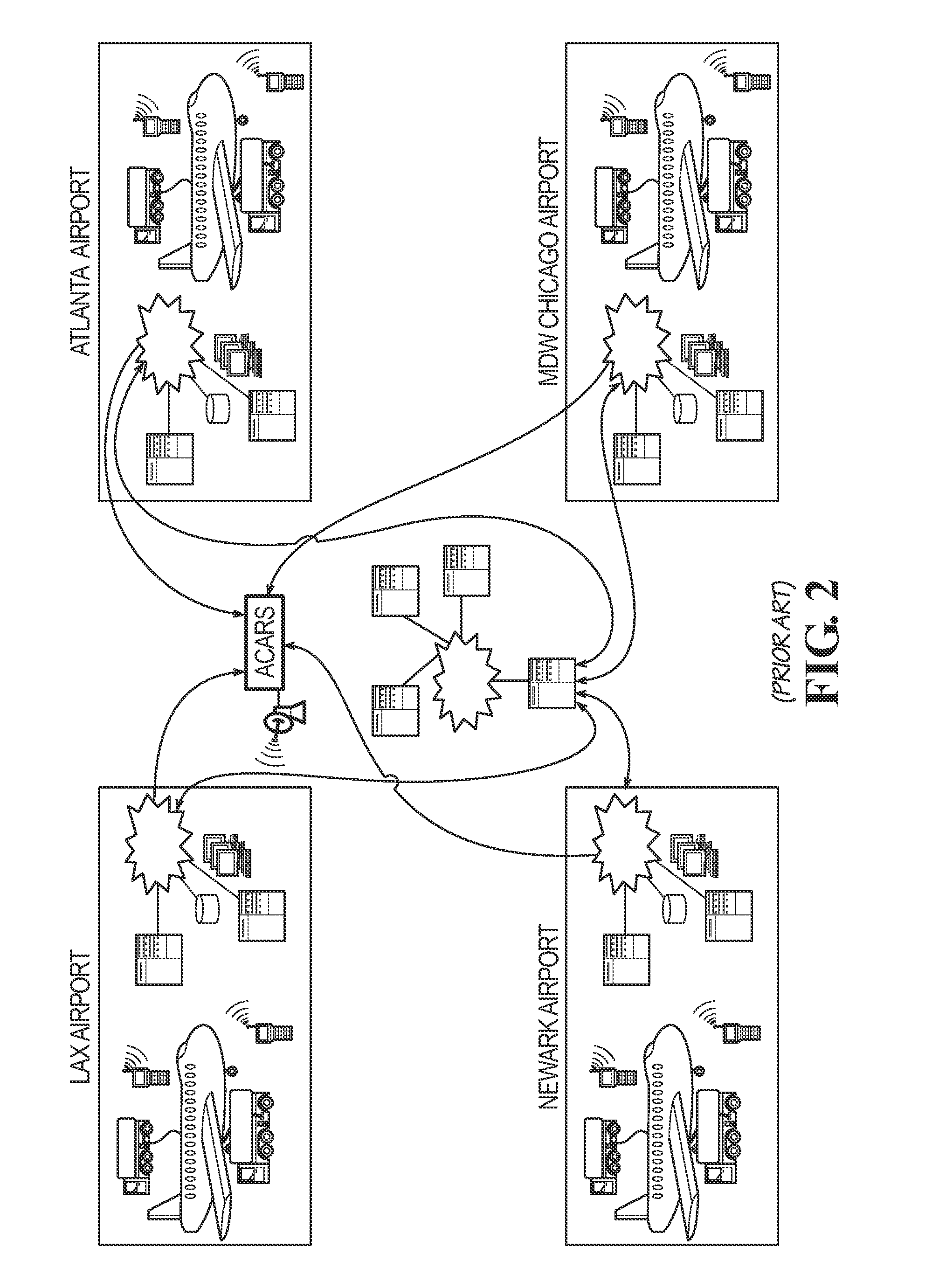
[0026]Turning now to the drawing figures, wherein like reference numerals represent like parts throughout the several views, FIGS. 1 and 2 depict a prior art fuel management system as described in the Background portion herein.

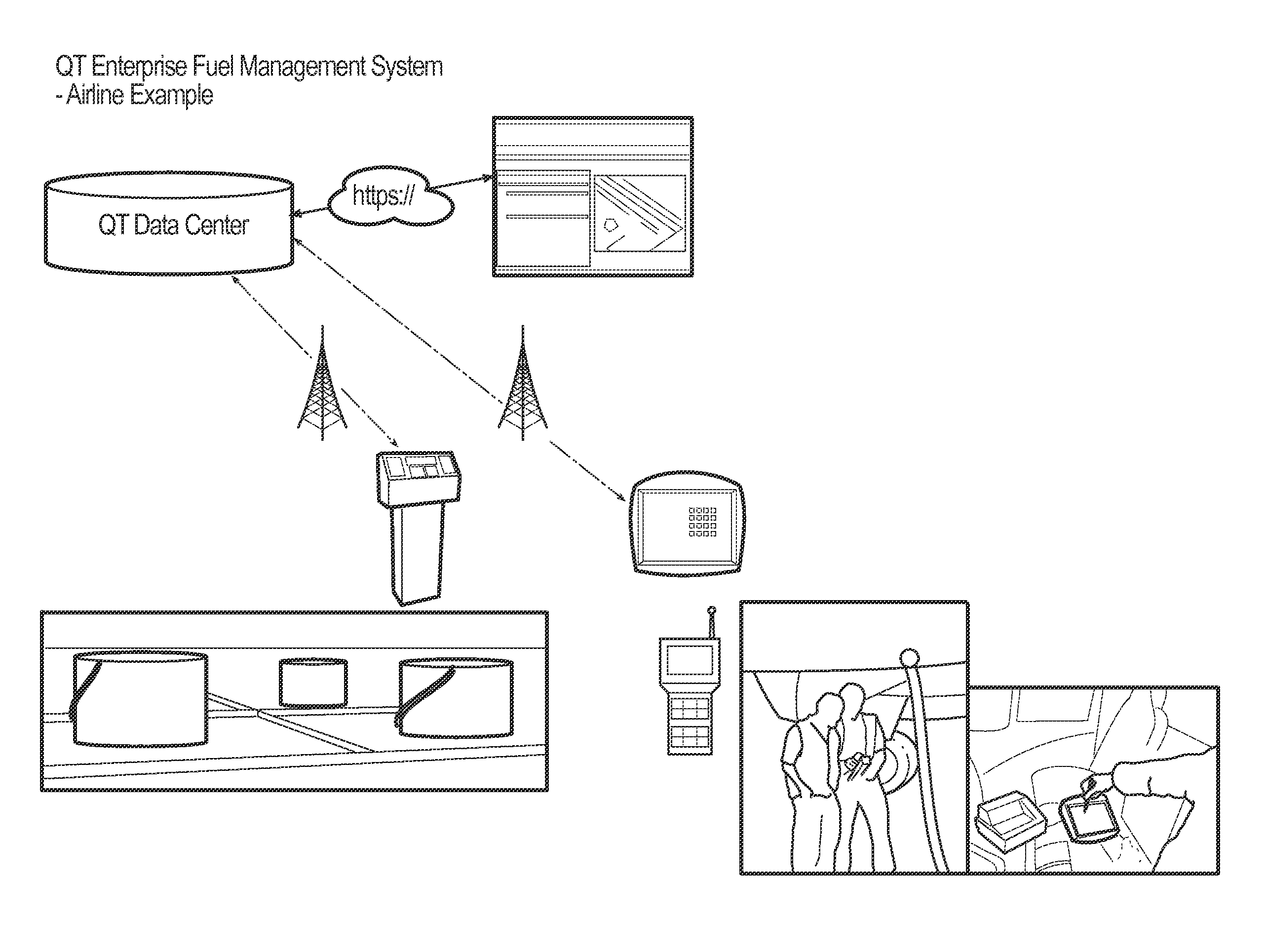
[0027]By contrast, as shown in FIG. 3 et seq., an enterprise fuel management system 100 is depicted. The enterprise fuel management system 100 is adapted for managing fueling operations of an aircraft fleet operated by a fleet operator having a central computer system at a data center ADC for operating aircraft at multiple airports. The system 100 includes a central data center 110 in communication with the fleet operator's central computer system ADC for forwarding data to the fleet operator's central computer system (e.g., the airline data center). The system 100 also includes, at each airport, one or more data collection units, such as data collection units 121, 122, 123, for collecting fueling information and forwarding it to the central data center 110. T...


PUM


Abstract

An enterprise fuel management system for managing fueling operations of an aircraft fleet operated by a fleet operator having a central computer system at a data center and operating aircraft at multiple airports avoids reliability problems associated with synchronizing a central database with local databases. Data collection units communicate collected fueling information wirelessly to a central data center, and the data collection units are not in direct communication with the fleet operator's central computer system. Moreover, the central data center gathers fueling information from the various data collection units and communicates the gathered fueling information to the fleet operator's central computer system as data messages for subsequent processing and action. In this way, the fleet operator's central computer system can maintain the only database of fueling information and flight information, obviating the need to synchronize the data in the fleet operator's computer system with data in some other computer system.

Description

CROSS-REFERENCE TO RELATED APPLICATION[0001]This application claims the priority benefit of U.S. Provisional Patent Application Ser. No. 61 / 428,471, filed Dec. 30, 2010, which is hereby incorporated herein by reference.TECHNICAL FIELD[0002]The present invention relates to a fuel management system for users of fuels, such as aviation fleets.BACKGROUND OF THE INVENTION[0003]In the past, it has been known to attempt fuel management at airports using a more or less decentralized approach. An example of such is shown in U.S. Pat. No. 7,376,495, which shows and describes a system that collects data with a hand-held computer (the so-called fueling agent client device) and forwards it to a local server (the “fuel management server”102).[0004]As shown in FIG. 1 of the 7,376,495 patent and as described in its specification, the system taught by the patent is a client-server arrangement in which the server 102 collects information from an external airline computer system, collects data from th...

Claims


Application Information

Patent Timeline
Patent Type & Authority Applications(United States)
IPC IPC(8): G06F19/00
CPCG06Q10/06
Inventor PORTOCALIS, GERASIMOS A.MOSER, GAIL A.WRIGHT, JAMES R.
Owner QT TECH
Why Eureka
Try Eureka