Tooling and a method for hot forging pieces of sheet metal

a technology of hot forging and tooling, which is applied in the direction of tool carrier control devices, forging/hammering/pressing machines, and shape tools, etc., can solve the problems of inability to accurately control the inside shape of the cavity in the reinforcement, the thickness of the sheet metal pieces formed in this way, and the duration and cost of such operations are relatively high. , to achieve the effect of simple, effective and inexpensiv

Active Publication Date: 2012-07-12
SN DETUDE & DE CONSTR DE MOTEURS DAVIATION S N E C M A
View PDF2 Cites 23 Cited by
  • Summary
  • Abstract
  • Description
  • Claims
  • Application Information

AI Technical Summary

Benefits of technology

[0018]A particular object of the invention is to provide a solut

Problems solved by technology

That method does not make it possible to control the inside shape of the cavity in the reinforcement with accuracy.
Nevertheless, it is difficult to control accurately the shape, the thicknesses, and the surface states of the sheet metal pieces as fo

Method used


Image

  • Tooling and a method for hot forging pieces of sheet metal
  • Tooling and a method for hot forging pieces of sheet metal
  • Tooling and a method for hot forging pieces of sheet metal

Examples


Embodiment Construction

[0050]The method of the invention consists initially in cutting out a piece from plane sheet metal of substantially constant thickness, e.g. by water-jet cutting. The sheet is made of a titanium-based alloy, for example TA6V.

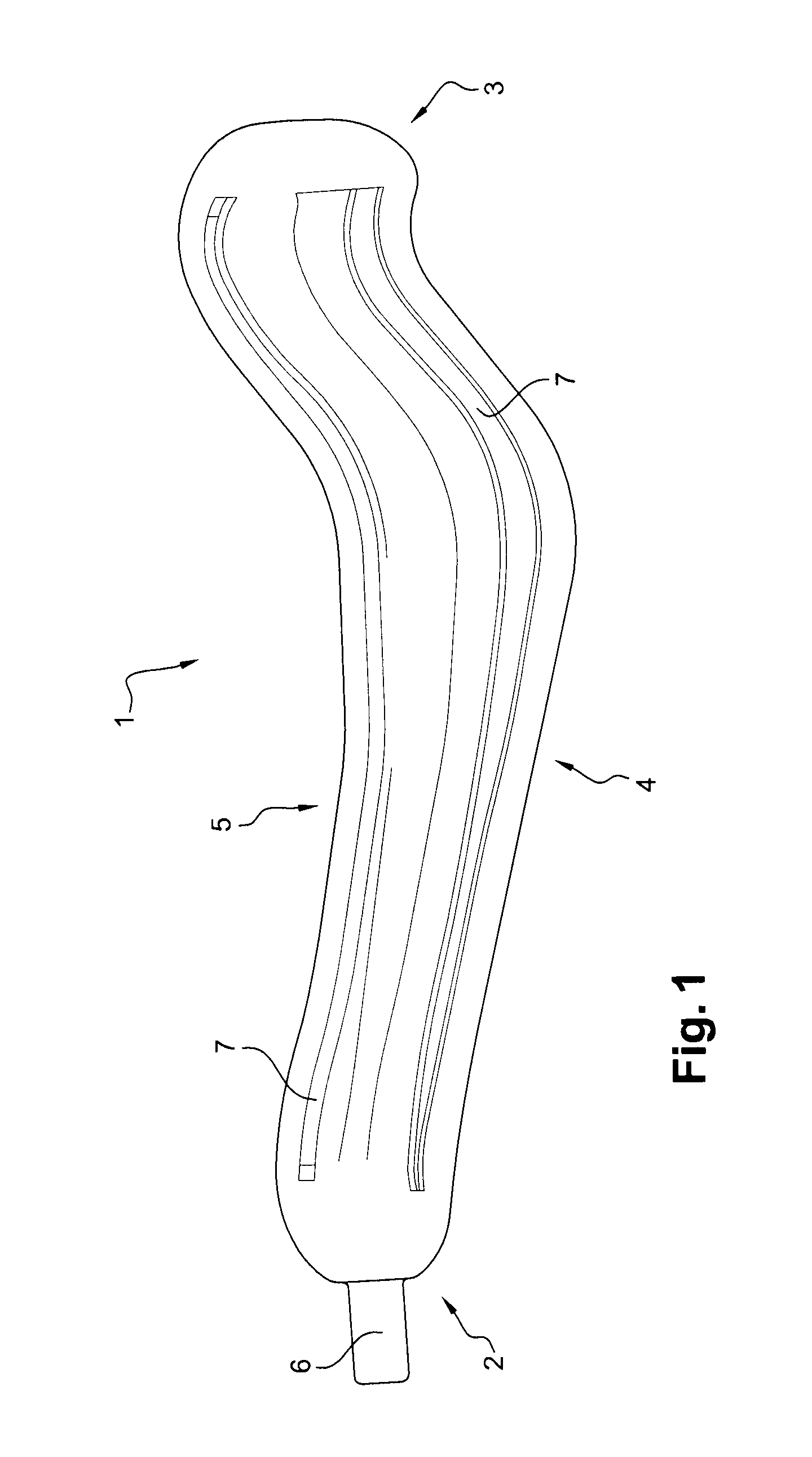
[0051]The piece 1 obtained after cutting out is shown in FIG. 1. It is of elongate and curved or S-shape, and it presents a periphery formed by two ends 2, 3 and two side edges 4, 5.

[0052]The end 2 is provided with a plane grip tongue 6 that extends outwards.

[0053]On one and / or the other of its bottom and top faces, the piece 1 may include zones 7 of different thicknesses, which may project or be indented. These curved or S-shaped zones 7 extend substantially in the longitudinal direction of the piece and they are approximately parallel to its side edges.

[0054]These zones 7 may be obtained by machining the piece 1 while flat, e.g. by milling it. The plane sheet metal 1 may be machined before or after the cutting-out operation.

[0055]The piece 1 is then heated to ...


PUM

PropertyMeasurementUnit
Heightaaaaaaaaaa

Abstract

The invention provides tooling and a method for hot forging pieces of sheet metal that are to form metal reinforcement mounted on the leading or trailing edge of a turbine engine blade, by means of bottom and top matrices each presenting a twisted elongate surface for use in shaping an initially plane piece of sheet metal, the shaping surface of the bottom matrix presenting a high portion, a low portion, and two end zones. The bottom matrix includes studs for positioning and guiding the piece, the studs being situated at the periphery of the corresponding shaping surface.

Description

FIELD OF THE INVENTION[0001]The present invention relates to tooling and to a method for hot forging pieces of sheet metal that are to form metal reinforcement for mounting on the leading or trailing edge of a blade of a turbine engine, such as an airplane turboprop or turbojet.BACKGROUND OF THE INVENTION[0002]In order to reduce the weight and the cost of the blades of turbine engine fans, they are generally made out of composite material. Fan blades need to be capable of withstanding high levels of shock and impact because of their speed of rotation and because of collisions with particles or foreign bodies that may penetrate into the stream of air. For this purpose, composite blades are protected at their leading and / or trailing edges by metal reinforcement that is adhesively bonded to the airfoils of the blades.[0003]Document EP 1 547 270-A1, in the name of the applicant, describes a method of fabricating such reinforcement by superplastic forming and diffusion bonding (SPF / DB), ...

Claims


Application Information

Patent Timeline
IPC IPC(8): B21D37/12B23P15/00
CPCY10T29/37Y10T29/49336B21D37/12B21J13/02B21D11/14Y10T29/49996B21K31/00B21D53/78B21D43/26B21D22/02B21K3/04B21D22/022
Inventor LECONTE, GILBERT MICHEL MARINFRANCHET, JEAN-MICHEL PATRICK MAURICEKLEIN, GILLES CHARLES CASIMIRMAGNAUDEIX, DOMINIQUE
Owner SN DETUDE & DE CONSTR DE MOTEURS DAVIATION S N E C M A
Why Eureka
Try Eureka