Actuation signal for microactuator bounce and ring suppression

a micro-actuator and actuation signal technology, applied in the field of micro-electromechanical system (mems) micro-actuators, can solve the problems of excessive wear, increase the closing time, and degrade the circuit performance, and achieve the effect of reducing bouncing and ringing and reducing the least possible amount of bouncing

Active Publication Date: 2012-07-12
QORVO US INC
View PDF0 Cites 13 Cited by
  • Summary
  • Abstract
  • Description
  • Claims
  • Application Information

AI Technical Summary

Benefits of technology

[0013]The present disclosure provides a system and method for controlling positioning of a movable member of a micro-electro-mechanical system (MEMS) microactuator to reduce bouncing and ringing. The system includes a MEMS microactuator having a movable member relative to a fixed member, which is fixed to a substrate on which the MEMS microactuator resides. For example, in one embodiment, the MEMS microactuator is a MEMS switch, and the movable member is a cantilever. The system also includes control circuitry in communication with the MEMS microactuator, wherein the control circuitry is adapted to execute a method that increases an actuation signal from a first state to a second state to urge the movable member from a first position to a second position and hold the movable member in the second position. A rate of increase in the actuation signal is a positive slope with the lowest possible magnitude which will ensure full compliance with the predetermined application specification in the time allotted by that specification as the movable member moves from a first position to the second position. Using the lowest possible slope magnitude will ensure that the closing occurs with the smallest possible momentum and therefore will create the least possible amount of bouncing when using the simple positive slope waveform. For the purpose of this disclosure slope is defined as rise over run,
[0014]At some point, it is desirable to return the movable member to the first position. Therefore, the control circuitry is further adapted to decrease the actuation signal from the second state to the first state to release the movable member to the first position. In at least one embodiment, the rate of decrease for the actuation signal between the second state and the first state has a slope with a transition time that is not less than the inverse of one quarter of a natural frequency of the member in the first position as the movable member transitions from the second position to the first position.
[0015]In another embodiment, the control circuitry is further adapted to decrease the actuation signal from the second state to a third state to release the movable member to a third position and decrease the actuation signal from the third state to the first state to release the movable member to the first position. In this embodiment, the rate of decrease for the actuation signal from the second state to the third state can be as fast as or not less than the inverse of a quarter of a fixed-fixed natural mechanical frequency in which the both ends of the movable member are fixed. An example of a fixed-fixed movable member is a closed MEMS switch in which one end of the movable member is anchored and the other end has a contact that is firmly closed against a contact plate. In at least one embodiment, the rate of decrease for the actuation signal between the third state and the first state has a slope with a transition time that is not less than the inverse of one quarter of a natural frequency of the movable member in the first position as the movable member transitions from the from the third position to the first position.
[0016]In yet another embodiment, the control circuitry is further adapted to hold the movable member in the third position before decreasing the actuation signal between the third state and the first state. In this way energy stored in the movable member is further dissipated before proceeding from the third position to the first position.

Problems solved by technology

Such bouncing degrades circuit performance and effectively increases the closing time.
The dynamic closing forces may also be sufficient to damage both the contact portion 24 of the second conductive pad 26 as well as the cantilever contact 22, thus causing excessive wear, which results in a shortened operating life for the MEMS switch 12.
In practice however, process variation in the switch manufacture will reduce or eliminate the efficiency of a waveform to effect soft closing as described.
Circuits which can adapt to this process variation in the switch manufacture have been proposed but these represent additional cost and complexity.
Such ringing may degrade circuit performance and effectively increases the opening time.

Method used


Image

  • Actuation signal for microactuator bounce and ring suppression
  • Actuation signal for microactuator bounce and ring suppression
  • Actuation signal for microactuator bounce and ring suppression

Examples


Embodiment Construction

[0025]The embodiments set forth below represent the necessary information to enable those skilled in the art to practice the disclosure and illustrate the best mode of practicing the disclosure. Upon reading the following description in light of the accompanying drawing figures, those skilled in the art will understand the concepts of the disclosure and will recognize applications of these concepts not particularly addressed herein. It should be understood that these concepts and applications fall within the scope of the disclosure and the accompanying claims.

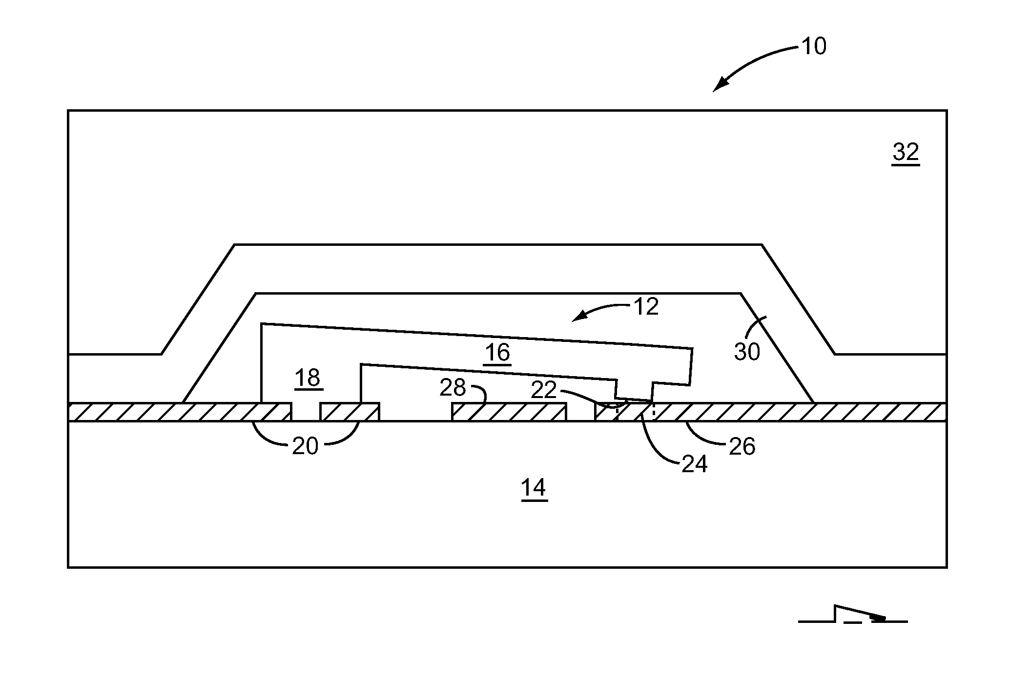
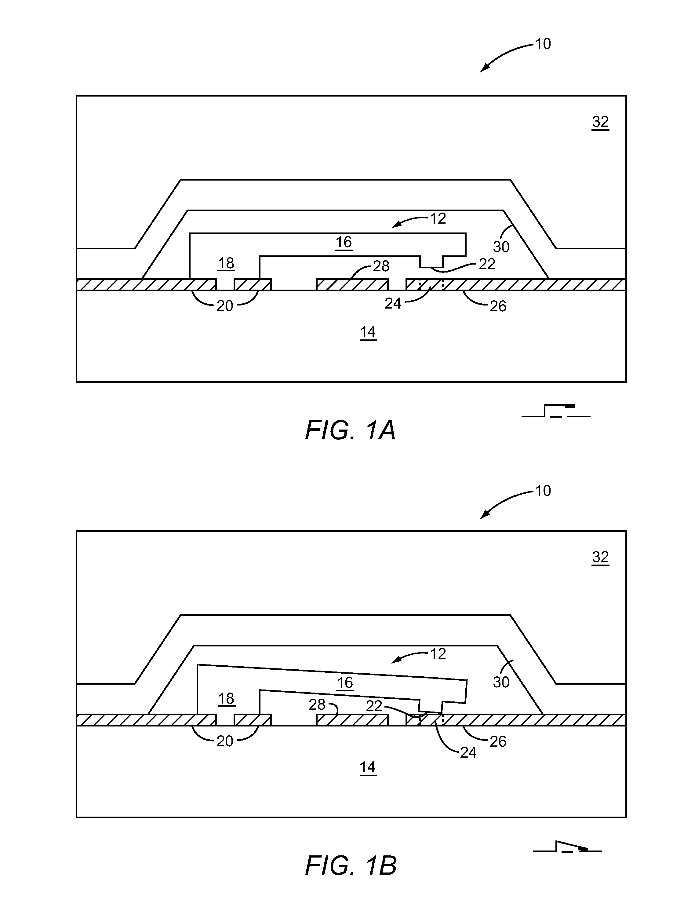
[0026]For the purposes of the present disclosure, directional terms such as “front”, “back”, “top”, “bottom”, “above”, “below”, “left”, “right”, “horizontal”, “vertical”, “up”, “down”, “upward”, “downward”, etc. are merely used for convenience in describing the various embodiments of the present disclosure. It is to be understood that the embodiments of the present disclosure may be oriented in various ways.

[0027]The system and...


PUM


Abstract

The present disclosure provides a system and method for controlling positioning of a movable member of a MEMS microactuator to reduce bouncing and ringing. The system includes control circuitry in communication with the MEMS microactuator. The control circuitry is adapted to linearly increase an actuation signal from a first state to a second state to urge the movable member from a first position to a second position and hold the movable member in the second position. The control circuitry is further adapted to linearly decrease the actuation signal from the second state to the first state to release the movable member to the first position. A transition time is not less than the inverse of one quarter of a natural frequency of the movable member as the movable member moves to the first position.

Description

[0001]This application claims the benefit of U.S. provisional patent application Ser. No. 61 / 431,692 filed Jan. 11, 2011 and U.S. provisional patent application Ser. No. 61 / 432,063 filed Jan. 12, 2011, the disclosures of which are incorporated herein by reference in their entireties.CROSS-REFERENCE TO RELATED APPLICATIONS[0002]This application is related to U.S. patent application Ser. No. 12 / 117,976 entitled CONTROLLED CLOSING OF MEMS SWITCHES filed May 9, 2008 and U.S. patent application Ser. No. 12 / 118,031 entitled CONTROLLED OPENING OF MEMS SWITCHES filed May 9, 2008, both of which are incorporated herein by reference in their entireties, and form part of the specification and teachings herein.FIELD OF THE DISCLOSURE[0003]The present disclosure relates to micro-electro-mechanical system (MEMS) microactuators, and in particular to controlling actuation of MEMS microactuators to improve performance.BACKGROUND OF THE DISCLOSURE[0004]As electronics evolve, there is an increased need...

Claims


Application Information

Patent Timeline
Patent Type & Authority Applications(United States)
IPC IPC(8): H02N1/00H01H59/00
CPCB81B7/008H01H1/50B81B2201/014B81B2203/0118H01H59/0009H01H1/0036
Inventor HAMMOND, JONATHAN HALEGORISSE, PHILIPPE
Owner QORVO US INC
Why Eureka
Try Eureka