Pressure control valve arrangement having an eccentrically mounted double magnet

a technology of eccentric mounting and pressure control valve, which is applied in the direction of diaphragm valve, valve details, braking systems, etc., can solve the problems of reducing the effective flow diameter and entail additional costs for producing and mounting the reducing sleeves, so as to achieve the effect of simple manufacturing and assembly and more cost-effectiveness

Inactive Publication Date: 2012-07-12
KNORR-BREMSE SYST FUER NUTZFAHRZEUGE GMBH
View PDF6 Cites 11 Cited by
  • Summary
  • Abstract
  • Description
  • Claims
  • Application Information

AI Technical Summary

Benefits of technology

[0008]The subject on which the exemplary embodiments and / or exemplary methods of the present invention are based is to develop a pressure control valve arrangement of the type initially mentioned in such a way that it can be manufactured and assembled more simply and more cost-effectively.

Problems solved by technology

However, because a correspondingly large diameter of the pressure medium connection is unfavorable in flow terms, in practice a reducing sleeve which reduces the effective flow diameter is inserted into the pressure medium connection.
However, this procedure entails additional costs for producing and mounting the reducing sleeve, and, in view of the large number of pressure control valve arrangements delivered by a supplier of vehicles, this amounts in total to a relatively high sum.

Method used


Image

  • Pressure control valve arrangement having an eccentrically mounted double magnet
  • Pressure control valve arrangement having an eccentrically mounted double magnet
  • Pressure control valve arrangement having an eccentrically mounted double magnet

Examples


Embodiment Construction

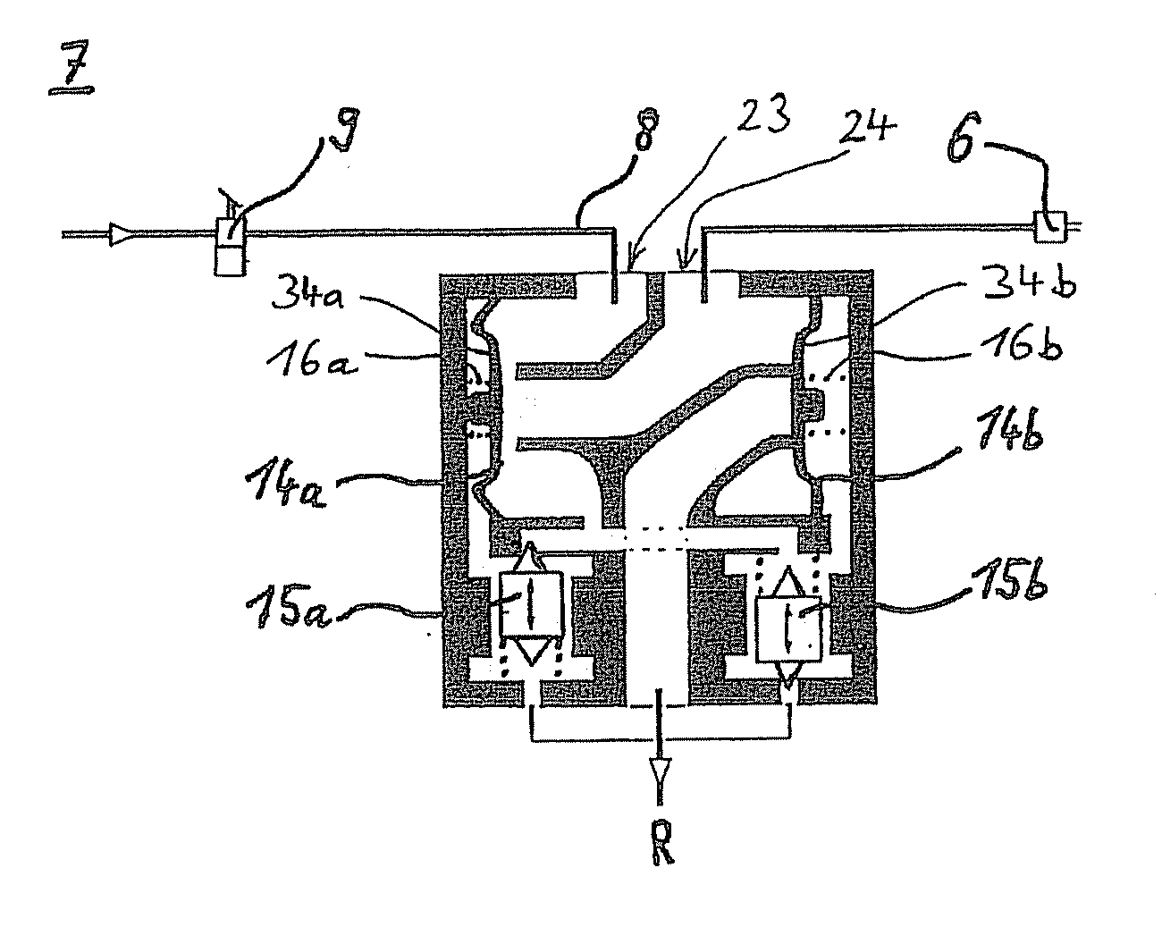
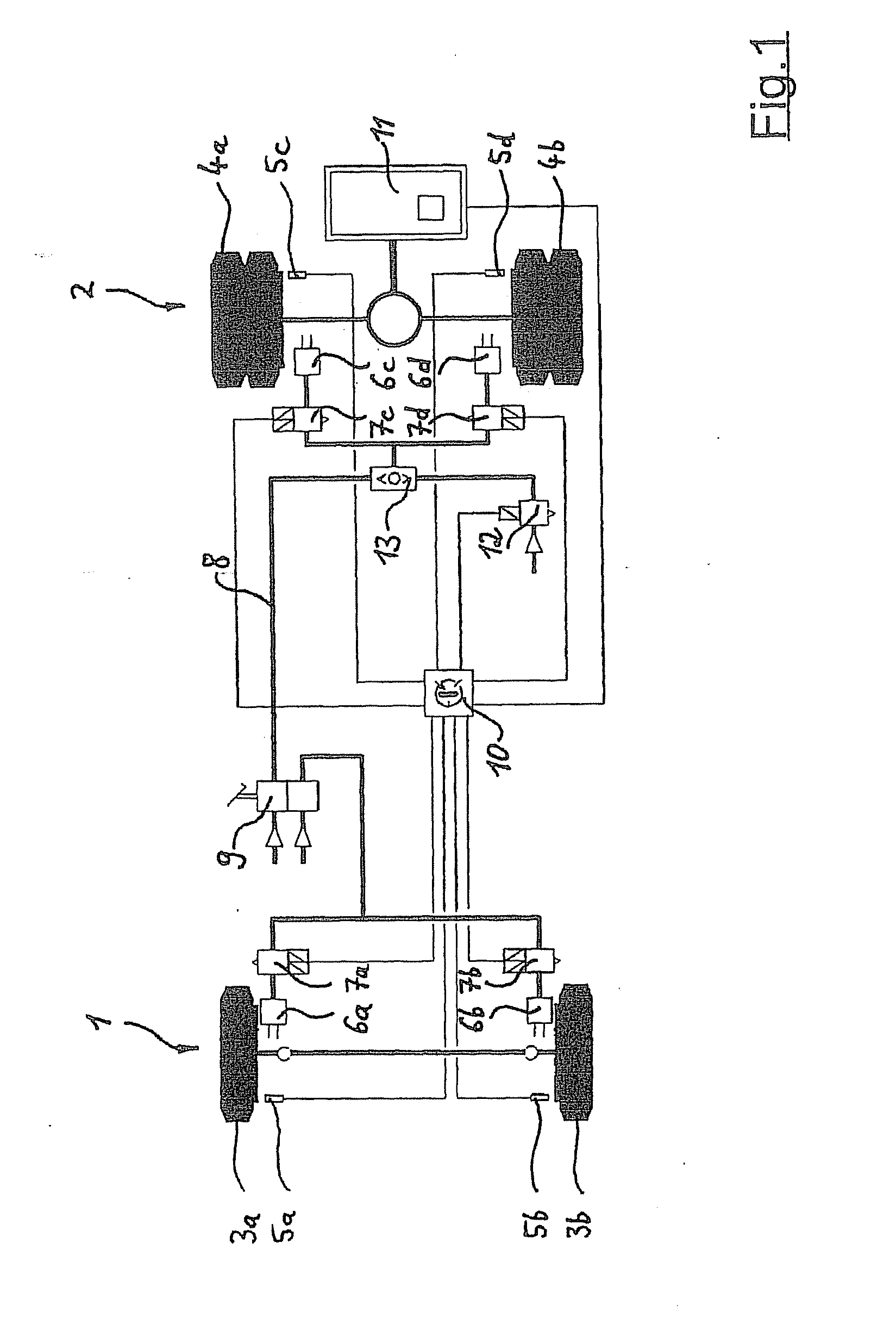
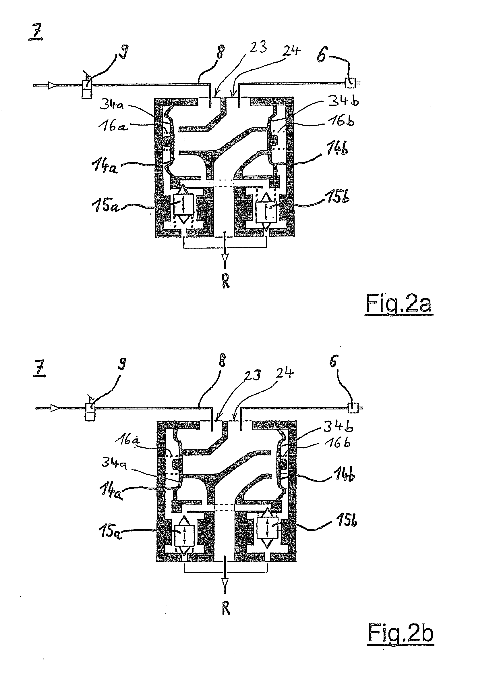
[0029]According to FIG. 1, a vehicle equipped with an ABS brake system has a front axle 1 and a rear axle 2. Wheels 3a and 3b are arranged on the front axle 1; the rear axle 2 has, for example, wheels 4a and 4b in each case equipped with twin tires. The ABS brake system serving for braking these wheels 3a, 3b and 4a, 4b is designed here in the manner of a 4S / 4C system (four sensors, four channels). This means that, overall, four rotational speed sensors 5a-5d and four pressure control valve arrangements 7a-7d are available here. The pressure control valve arrangements 7a-7d serve for the activation of respectively assigned brake cylinders 6a-6d. All the pressure control valve arrangements 7a-7d are connected to a foot-operated brake valve 9 via a branching pneumatic brake pressure line 8.

[0030]The driver, when actuating the foot-operated brake valve 9, generates a brake pressure which, passing through the pressure control valve arrangements 7a-7d, is transferred by the pneumatic bra...


PUM


Abstract

A pressure control valve arrangement is described for controlling the fluid pressure in an ABS brake system of a vehicle so that, during a tendency of individual wheels of the vehicle to lock, the brake pressure in at least one assigned brake cylinder can be matched adaptively, a) two diaphragm valves and two electromagnetic control valves, activatable by an electronic control device, for the pilot control of the diaphragm valves being provided in the housing of the pressure control valve arrangement, b) the two electro-magnetic control valves having a double magnet with two magnet coils and also magnet armatures cooperating with solenoid valve seats and actuable by current being applied to the magnet coils, c) the housing having at least one pressure medium connection, connected to a service brake valve, for acting with pressure upon and/or relieving the pressure of the pressure control valve arrangement and also at least one working connection for connecting to the brake cylinder, characterized in that d) a plane of symmetry of the mid-axes of the magnet coils of the double magnet of the electromagnetic control valves is arranged parallel, and offset by the amount of an eccentricity, with respect to a mid-axis of the pressure medium connection.

Description

FIELD OF THE INVENTION[0001]The present invention relates to a pressure control valve arrangement for controlling the fluid pressure in an ABS brake system of a vehicle.BACKGROUND INFORMATION[0002]ABS (antilock system) prevents the wheels from locking and comes into operation when greater adhesion than is transferable is demanded between a tire and the road, that is to say when the driver overbrakes. In overbraking, the central electronic control apparatus of the ABS brake system detects from rotational speed sensor signals the tendency of one or more wheels to lock and from this calculates the activation of the pressure control valve arrangement acting upon the assigned brake cylinder. The brake pressure is then set to optimal slip by the pressure control valve arrangement by lowering, holding or building up the brake pressure according to the wheel behavior and therefore the frictional conditions between the tire and road.[0003]ABS pressure control valve arrangements without a rel...

Claims


Application Information

Patent Timeline
Patent Type & Authority Applications(United States)
IPC IPC(8): B60T8/34B60T15/02B60T8/36
CPCB60T15/027B60T8/3605F16K7/17F16K27/0263F16K31/0675
Inventor GREBE, JANBRENNER, DIRKWEIPPERT, JOCHENROHN, WOLFGANGJAEHNS, HARALD
Owner KNORR-BREMSE SYST FUER NUTZFAHRZEUGE GMBH
Why Eureka
Try Eureka