Method and Apparatus for a Half-Bridge Variable Differential Transformer Position Sensing System

Active Publication Date: 2012-07-12
WOODWARD MPC
View PDF4 Cites 17 Cited by
  • Summary
  • Abstract
  • Description
  • Claims
  • Application Information

AI Technical Summary

Benefits of technology

[0007]In one aspect, embodiments of the invention provide a half-bridge variable differential transformer position sensing system that includes a transducer having a stator with an inductive coil having a center tap configured to provide an output signal. The transducer also has an armature with a magnetically permeable core configured to move within the inductive coil, such that movement of the magnetically permeable core causes a change in the output signal. The position sensing system includes a first circuit configured to provide an excitation signal at one terminal of the inductive coil. The position sensing system further includes a microcontroller configured to calculate the degree of change in the position of the magnetically permeable core based on a comparison of a voltage of the output signal and a voltage of the excitation signal. Further, the microprocessor is configured to correct for variations in the voltage of the output signal due to the temperature of the transducer and due to non-linear effects on the output signal caused by movement of the magnetically permeable core. Further, no more than three electrical wires are used to operate the half-bridge variable differential transformer position sensing system.

Problems solved by technology

Further, no more than three electrical wires are used to operate the half-bridge variable differential transformer position sensing system.

Method used


Image

  • Method and Apparatus for a Half-Bridge Variable Differential Transformer Position Sensing System
  • Method and Apparatus for a Half-Bridge Variable Differential Transformer Position Sensing System
  • Method and Apparatus for a Half-Bridge Variable Differential Transformer Position Sensing System

Examples


Embodiment Construction

[0028]Conventional new position transducers that attempt to reduce the number of wires connected to the transducer may sacrifice the reliability, or at the very least the accuracy and self-compensating features of a conventional linear variable differential transformer (LVDT) and a conventional rotational variable differential transformer (RVDT). This may require that these features be brought in by the end user of these sensors through additional custom electronics and additional application software. This tends to result in increased parts count and greater complexity of the overall system, and, therefore, reduced reliability. It also tends to shift the burden of correcting these transducer errors to the end user.

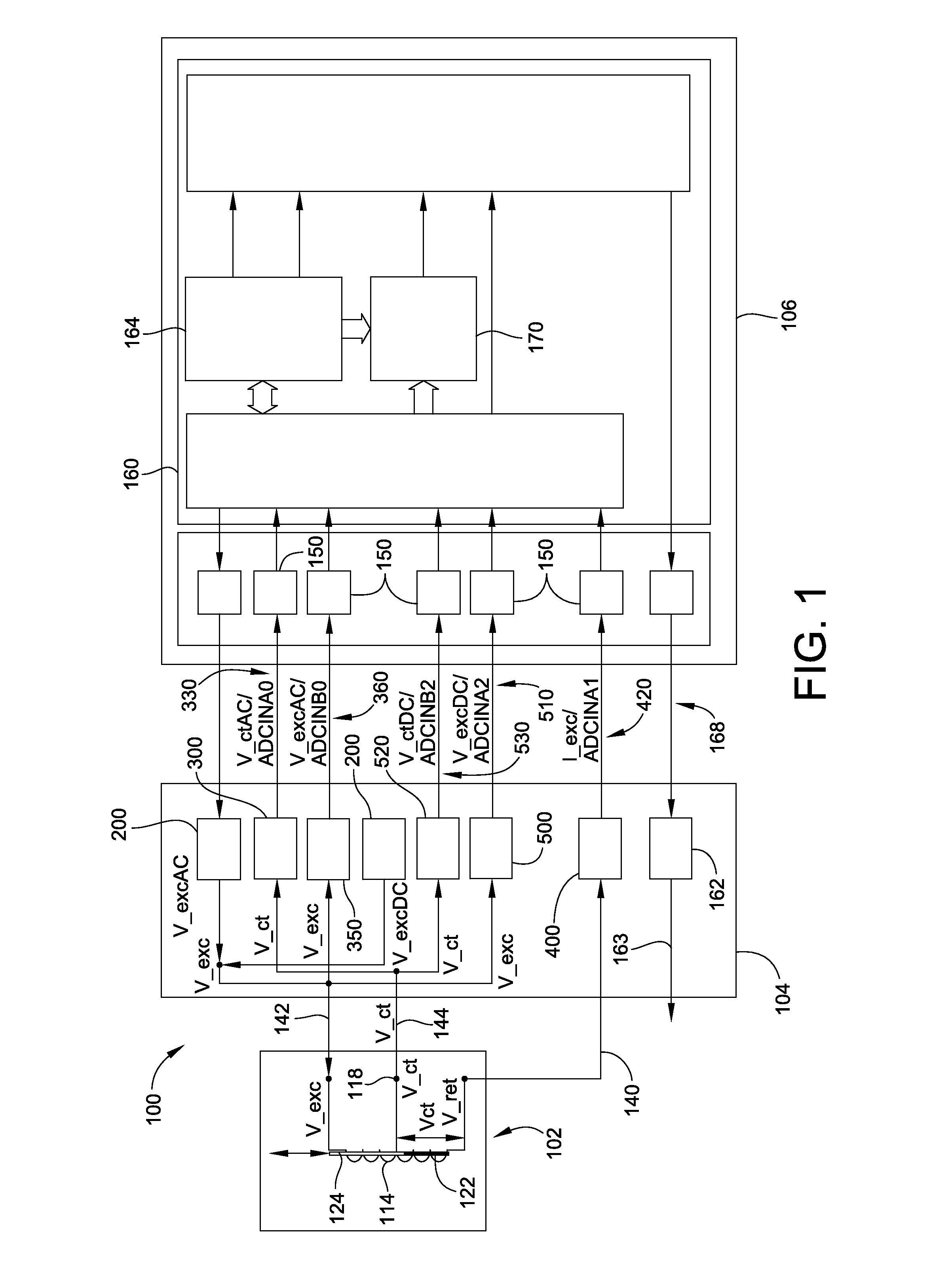
[0029]FIG. 1 shows a schematic system block diagram for a half-bridge variable differential transformer position sensing system 100, also called a half-bridge LVDT, to measure linear displacements, according to an embodiment of the invention. A transducer 102 is shown to ...


PUM


Abstract

A half-bridge variable differential transformer position sensing system that includes a transducer having a stator with an inductive coil having a center tap configured to provide an output signal. The transducer also has an armature with a magnetically permeable core configured to move within the inductive coil, such that movement of the magnetically permeable core causes a change in the output signal. The position sensing system includes a first circuit configured to provide an excitation signal at one terminal of the inductive coil. The system includes no more than three electrical interface wires, and a microcontroller configured to calculate the degree of change in the position of the magnetically permeable core, and is configured to correct for variations in the voltage of the output signal due to the temperature of the transducer and due to non-linear effects on the output signal caused by movement of the magnetically permeable core.

Description

CROSS-REFERENCE TO RELATED PATENT APPLICATIONS[0001]This patent application claims the benefit of U.S. Provisional Patent Application No. 61 / 430,847, filed Jan. 7, 2011, the entire teachings and disclosure of which are incorporated herein by reference thereto.FIELD OF THE INVENTION[0002]This invention generally relates to position sensors, and, more particularly, to position sensors suitable for aerospace applications.BACKGROUND OF THE INVENTION[0003]In aerospace applications, it is generally desirable to minimize the weight of all components on an aircraft. Less weight translates into reduced fuel consumption and lower operating costs. Two commonly used position sensors for aerospace applications are the linear variable differential transformer (LVDT) and the rotary variable differentiable transformer (RVDT). These types of sensors are used in aerospace applications particularly due to their ability to perform under harsh environmental conditions with high reliability and accuracy....

Claims


Application Information

Patent Timeline
Patent Type & Authority Applications(United States)
IPC IPC(8): G01B7/14
CPCG01B7/003
Inventor SZULYK, ZENON P.JAYARAMAN, GANGA P.HAHN, BRIAN M.
Owner WOODWARD MPC
Why Eureka
Try Eureka