Method of inspecting power storage device and method of producing the same

a technology of power storage device and inspection method, which is applied in the direction of secondary battery servicing/maintenance, sustainable manufacturing/processing, instruments, etc., can solve the problems of inability to produce significant voltage reduction, inability to ignore the variations in contact resistance between different measurements, and inability to determine the quality of secondary batteries. , to achieve the effect of short inspection time, short inspection time and optimized circuit resistance calculation

Active Publication Date: 2020-01-23
TOYOTA JIDOSHA KK
View PDF0 Cites 1 Cited by
  • Summary
  • Abstract
  • Description
  • Claims
  • Application Information

AI Technical Summary

Benefits of technology

[0013]When the resistance value of the resistor can be varied, a variable resistance setting process can be performed, more specifically, the resistance value of the resistor is set to a large value when the storage capacity of the power storage device to be inspected is small, and is set to a small value when the storage capacity is large. In this manner, the accuracy in calculation of the circuit resistance value can be optimized. Since the accuracy of the circuit resistance value thus measured is high, the inspection time can be further shortened.
[0014]According to a method of producing a power storage device according to a second aspect of the disclosure, the power storage device is produced by assembling the power storage device (assembling step), and carr

Problems solved by technology

However, it takes time to determine the quality of the secondary battery in the known method as described above.
This is because a significant amount of reduction of the voltage cannot be produced unless the secondary battery is left to stand for a long period of time in the leaving step.
Thus, unless the voltage reduction amount itself is large to some extent, variations in the contact resistance among different measurements cannot be ignored.
Further, the accuracy of voltage measurement is not so good, because the voltage measurement is inevitably subjected to an influence of voltage drop in a current-carrying path at the time of measurement.
Nonetheless, simply replacing voltage measurement with current measurement does not

Method used


Image

  • Method of inspecting power storage device and method of producing the same
  • Method of inspecting power storage device and method of producing the same
  • Method of inspecting power storage device and method of producing the same

Examples


Embodiment Construction

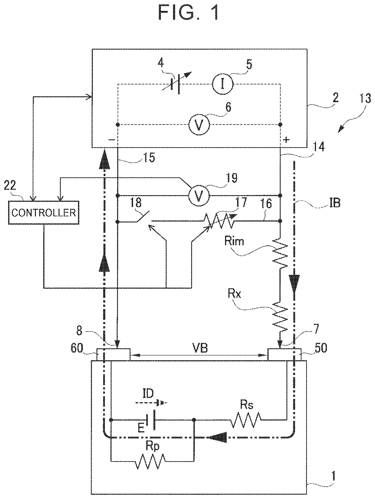
[0029]One embodiment of the disclosure will be described in detail with reference to the drawings. In this embodiment, the disclosure is embodied as an inspecting method conducted by using an inspection system 13 illustrated in a circuit diagram of FIG. 1. The inspection system 13 of FIG. 1 has a power-supply unit 2, positive-side conductor 14, negative-side conductor 15, and resistance path 16. The positive-side conductor 14 and the negative-side conductor 15 are respectively connected to a positive terminal and a negative terminal of the power-supply unit 2. Probes 7, 8 are provided at distal ends of the positive-side conductor 14 and negative-side conductor 15, respectively. The resistance path 16 is disposed between the positive-side conductor 14 and the negative-side conductor 15. In the resistance path 16, a resistor 17 and a switch 18 are arranged in series. The resistor 17 is a variable resistor.

[0030]The inspection system 13 further has a voltmeter 19. The voltmeter 19 is d...


PUM


Abstract

A circuit is formed by connecting positive terminals and negative terminals of a power storage device and an external power supply, and a resistor and a switch are arranged in series between a positive-side conductor and a negative-side conductor. An ON time for which the switch is temporarily closed before start of inspection is made longer as the capacity of the power storage device is larger. An ON voltage between the positive-side and negative-side conductors within the ON time, and an OFF voltage between these conductors at a time other than the ON time are obtained, and a parasitic resistance value of the circuit is calculated based on the ON and OFF voltages and a resistance value of the resistor. During the inspection, the voltage of the external power supply, which is applied to the power storage device, is increased according to the parasitic resistance value.

Description

INCORPORATION BY REFERENCE[0001]The disclosure of Japanese Patent Application No. 2018-136100 filed on Jul. 19, 2018 including the specification, drawings and abstract is incorporated herein by reference in its entirety.BACKGROUND1. Technical Field[0002]The disclosure relates to an inspecting method for determining the quality of a power storage device. More particularly, the disclosure relates to a method of inspecting a power storage device, with which the quality can be determined with appropriate accuracy according to various conditions, based on an amount of discharge current, rather than an amount of voltage reduction of the power storage device. The disclosure also relates to a method of producing the power storage device, which method includes the inspecting method.2. Description of Related Art[0003]Various inspection technologies for determining the quality of a secondary battery, or other power storage devices, have been proposed. For example, in a method described in Japa...

Claims


Application Information

Patent Timeline
IPC IPC(8): G01R31/389G01R31/36H01M10/42
CPCH01M10/4285G01R31/389G01R31/3644G01R31/3865H01M10/0404H01M10/48G01R31/392G01R31/386Y02E60/10Y02P70/50
Inventor GOTO, TAKESHIKOBAYASHI, KIWAMU
Owner TOYOTA JIDOSHA KK
Why Eureka
Try Eureka