Fuel cell system and method of controlling the same

a fuel cell and system technology, applied in the direction of fuel cell control, fuel cell, electric generators, etc., can solve the problems of increasing the variation in the cell voltage, the inability to perform cathode gas supply to the fuel cell stack and the stop of the supply, etc., to reduce the amount of cathode gas supplied by the turbo compressor, the effect of less likely or unlikely to excessively ris

Active Publication Date: 2019-05-09
TOYOTA JIDOSHA KK
View PDF2 Cites 1 Cited by
  • Summary
  • Abstract
  • Description
  • Claims
  • Application Information

AI Technical Summary

Benefits of technology

[0005]A fuel cell system according to a first aspect of the disclosure includes a fuel cell stack, a cathode gas supply passage through which cathode gas is supplied to the fuel cell stack, a cathode gas discharge passage through which the cathode gas is discharged from the fuel cell stack, a turbo compressor provided in the cathode gas supply passage and configured to deliver the cathode gas to the fuel cell stack, a valve provided in the cathode gas supply passage or the cathode gas discharge passage, and a controller configured to control constituent components of the fuel cell system including the turbo compressor and the valve. The controller is configured to perform cathode-gas flow rate change control to alternately open and close the valve, in a condition where the turbo compressor is driven, when the fuel cell stack is not required to generate electric power. In the fuel cell system of this aspect, supply of the cathode gas to the fuel cell stack and stop of the supply can be performed in short cycles, so that the amount of variation in the voltage of the cell stack can be reduced. Also, the fuel cell system uses the turbo compressor, and the amount of cathode gas supplied by the turbo compressor is reduced with increase in the pressure between the turbo compressor and the valve at the time of closing of the valve. Therefore, the pressure between the turbo compressor and the valve is less likely or unlikely to excessively rise, as compared with the case where a compressor of a volume compression type, such as roots type, is used.
[0006]In the fuel cell system according to the above aspect, the flow rate of the cathode gas delivered by the turbo compressor when the fuel cell stack is not required to generate electric power is smaller than the flow rate of the cathode gas delivered when the fuel cell stack is required to generate electric power. With the fuel cell system thus configured, the fuel efficiency is improved, as compared with the case where the flow rate of the cathode gas delivered by the turbo compressor when the fuel cell stack is not required to generate electric power is equal to the flow rate in the case where the fuel cell stack is required to generate electric power.
[0007]In the fuel cell system, the valve may be provided downstream of the turbo compressor in the cathode gas supply passage, or provided in the cathode gas discharge passage, and the turbo compressor may include a rotating body housing that houses a rotating body that delivers the cathode gas, a motor housing that houses a motor that drives the rotating body, a part of the motor housing being filled with oil, and a mechanical seal that inhibits the oil from seeping from the rotating body housing into the motor housing. With the fuel cell system thus configured, the turbo compressor provided with the mechanical seal can achieve high-speed rotation of the rotating body, and the pressure in the rotating body housing increases to be higher than the pressure in the motor housing when the valve is closed, so that the oil can be made less likely or unlikely to seep from the motor housing into the rotating body housing.

Problems solved by technology

In the system described in JP 2012-89523 A, supply of cathode gas to the fuel cell stack and stop of the supply cannot be performed in short cycles, because of large inertia of the air compressor, and the amount of variation in the cell voltage may be increased.

Method used


Image

  • Fuel cell system and method of controlling the same
  • Fuel cell system and method of controlling the same
  • Fuel cell system and method of controlling the same

Examples


first embodiment

A. First Embodiment

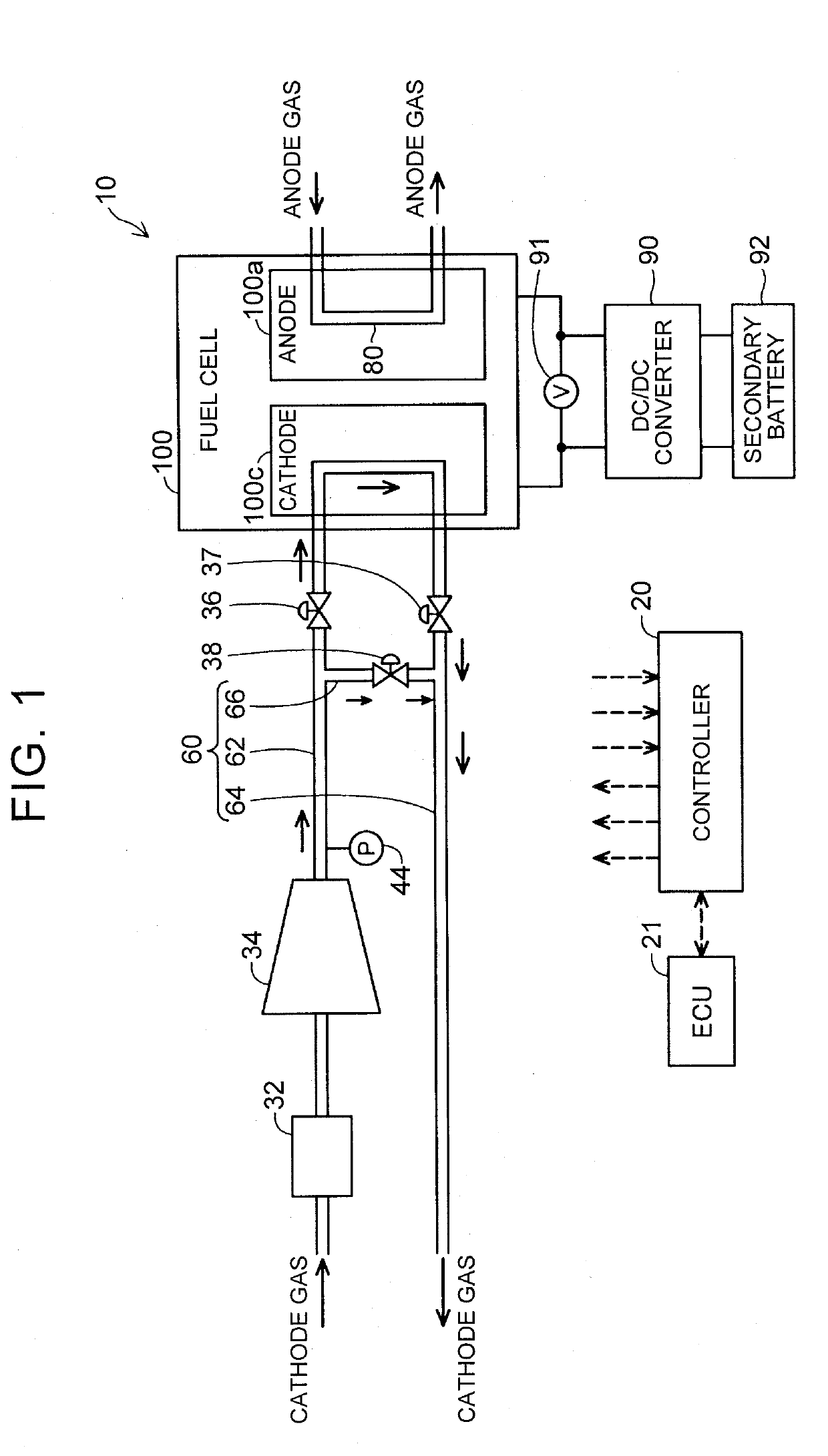
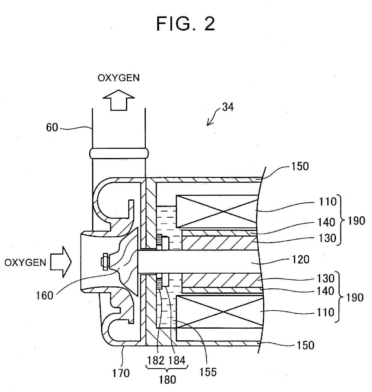
[0020]FIG. 1 shows a fuel cell system 10 as one embodiment of the disclosure. The fuel cell system 10 is installed on a fuel cell vehicle, for example. In this embodiment, the fuel cell system 10 includes a fuel cell stack 100, controller 20, air flow meter 32, turbo compressor 34, cathode gas passage 60, and anode gas passage 80.

[0021]The fuel cell stack 100 is a polymer electrolyte fuel cell that is supplied with anode gas (e.g., hydrogen gas) and cathode gas (e.g., air) as reaction gases, to generate electric power. The fuel cell stack 100 is composed of a plurality of unit cells (not shown) stacked together. The anode gas is supplied from an anode gas tank (not shown), and passes through the anode gas passage 80, to be supplied to an anode 100a of the fuel cell stack 100 and used for electrochemical reaction. A portion of the anode gas which was not used for electrochemical reaction is discharged as offgas to the outside of the fuel cell stack 100. On the othe...

second embodiment

B. Second Embodiment

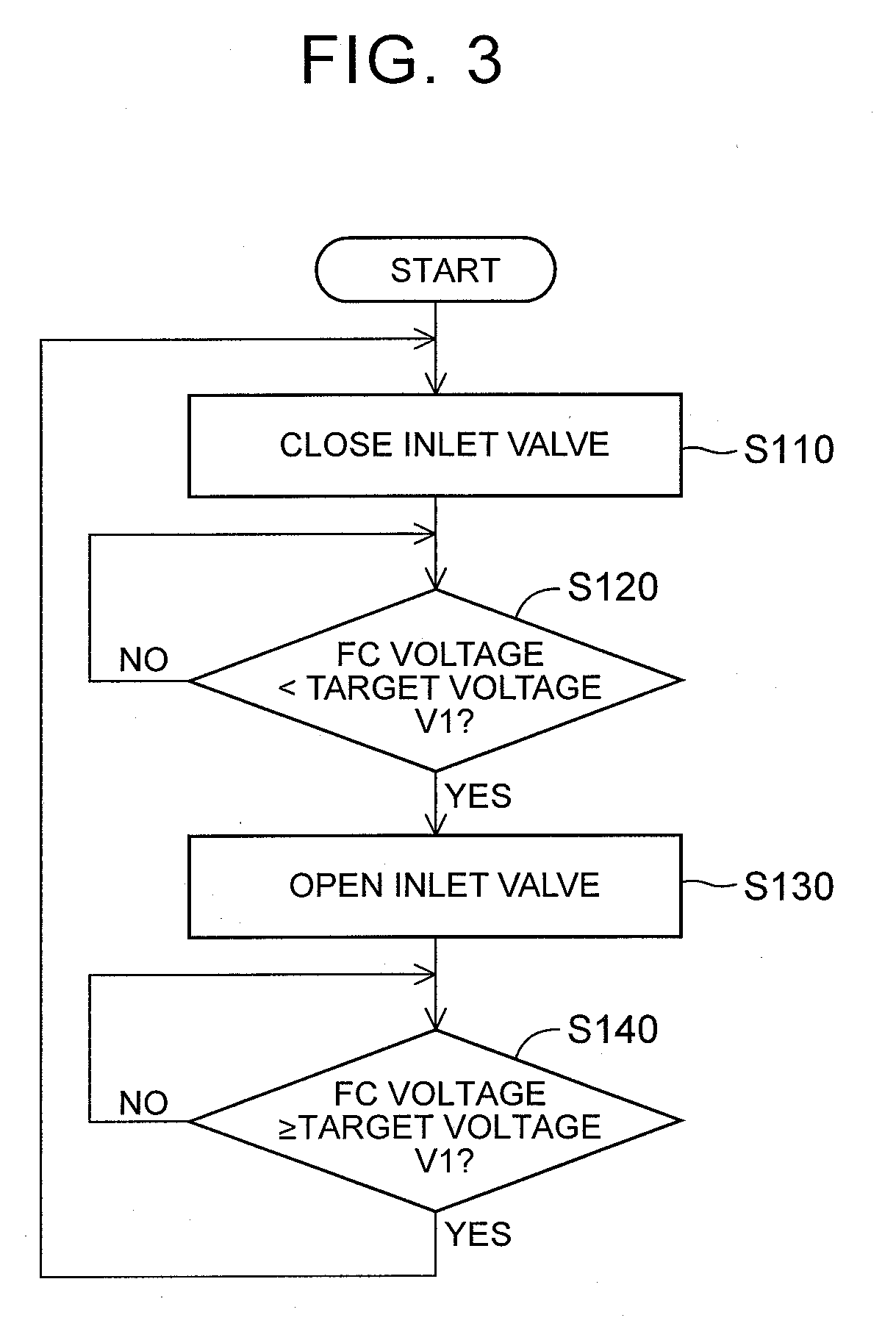
[0055]FIG. 5 is a flowchart of c cathode-gas flow rate change control according to a second embodiment. The second embodiment is different from the first embodiment in that step S105 and step S200 are additionally provided, but the first and second embodiments are identical with each other in other respects.

[0056]In the second embodiment, after the inlet valve 36 is closed (step S110), the controller 20 determines whether the operation to close the inlet valve 36 is performed for the first time under the current cathode-gas flow rate change control. When the operation to close the inlet valve 36 is performed for the first time under the current cathode-gas flow rate change control (step S105: YES), the controller 20 performs a malfunction determination process (step S200). On the other hand, when the operation to close the inlet valve 36 is not performed for the first time under the current cathode-gas flow rate change control (step S105: NO), the control proceed...

third embodiment

C. Third Embodiment

[0064]FIG. 8 is a flowchart of cathode-gas flow rate change control according to a third embodiment. The third embodiment is different from the first embodiment in that step S150 and step S160 are additionally provided, but is identical with the first embodiment in other respects.

[0065]In the third embodiment, when the controller 20 determines that the FC voltage is smaller than the target voltage V1 (step S140: NO), the controller 20 determines whether the FC voltage is smaller than a lower-limit voltage V2 (step S150). The lower-limit voltage V2 is a voltage at which the catalyst included in the fuel cell stack 100 switches between oxidation reaction and reduction reaction, for example, and is obtained in advance by experiment or simulation. In this embodiment, the controller 20 stores the lower-limit voltage V2 in advance. In this embodiment, the lower-limit voltage V2 is smaller than the target voltage V1.

[0066]When the controller 20 determines that the FC vol...


PUM

PropertyMeasurementUnit
flow rateaaaaaaaaaa
flow rateaaaaaaaaaa
flow rateaaaaaaaaaa

Abstract

A fuel cell system includes a cathode gas supply passage through which cathode gas is supplied to the fuel cell stack, a cathode gas discharge passage through which the cathode gas is discharged from the fuel cell stack, a turbo compressor provided in the cathode gas supply passage for delivering the cathode gas to the fuel cell stack, a valve provided in the cathode gas supply passage or the cathode gas discharge passage, and a controller that controls constituent components of the fuel cell system including the turbo compressor and the valve. The controller performs cathode-gas flow rate change control to alternately open and close the valve, in a condition where the turbo compressor is driven, when the fuel cell stack is not required to generate electric power.

Description

INCORPORATION BY REFERENCE[0001]The disclosure of Japanese Patent Application No. 2017-216003 filed on Nov. 9, 2017 including the specification, drawings and abstract is incorporated herein by reference in its entirety.BACKGROUND1. Technical Field[0002]The disclosure relates to a fuel cell system and a method of controlling the fuel cell system.2. Description of Related Art[0003]In a fuel cell system described in Japanese Unexamined Patent Application Publication No. 2012-89523 (JP 2012-89523 A), when a fuel cell stack is in a condition where electric power generation is stopped, cathode gas is intermittently supplied from an air compressor to the fuel cell stack, even during stop of power generation, so as to prevent the fuel cell stack from being unable to quickly respond to a request to generate electric power. In this manner, the voltage of a unit cell (which will be called “cell voltage”) is kept equal to or larger than a given value.SUMMARY[0004]In the system described in JP 2...

Claims


Application Information

Patent Timeline
Patent Type & Authority Applications(United States)
IPC IPC(8): H01M8/04111H01M8/04537H01M8/0438H01M8/04746H01M8/2465
CPCH01M8/04111H01M8/04559H01M8/04425H01M8/04753H01M8/04776H01M8/2465H01M2250/20H01M8/04201H01M8/043H01M8/04686H01M2008/1095Y02E60/50
Inventor NAMBA, RYOICHIKATAYAMA, YUSUKE
Owner TOYOTA JIDOSHA KK
Why Eureka
Try Eureka