Integrated high-frequency generator system utilizing the magnetic field of the target application

a generator system and target application technology, applied in wave based measurement systems, using reradiation, instruments, etc., can solve the problems of limited applicability of techniques, large and expensive superconducting magnets, and inability to efficiently extract mode out of microwave tubes or transport over long distances at low loss, so as to reduce the size or footprint of the overall system, reduce the number and cost of magnets, and facilitate and simply adapt to dnp operation

Active Publication Date: 2012-07-12
BRIDGE 12 TECH
View PDF3 Cites 14 Cited by
  • Summary
  • Abstract
  • Description
  • Claims
  • Application Information

AI Technical Summary

Benefits of technology

[0016]It is a further object of this invention to provide such a magnetic resonance device, which is easily and simply adapted for DNP operation.
[0017]It is a further object of this invention to provide such a high-frequency generator which is smaller, more compact and more efficient.
[0018]The invention results from the realization that an improved, integrated high-frequency generator system utilizing the magnetic field of the target app

Problems solved by technology

Such a mode cannot be efficiently extracted out of the microwave tube or transported over long distances at low loss.
This magnetic field is typically provided by a superconducting magnet which is large and expensive.
The first DNP experiments were performed in the early 1950s at low magnetic fields but until recently, the technique was of limited applicability because of the lack of high-frequency, hi

Method used


Image

  • Integrated high-frequency generator system utilizing the magnetic field of the target application
  • Integrated high-frequency generator system utilizing the magnetic field of the target application
  • Integrated high-frequency generator system utilizing the magnetic field of the target application

Examples


Embodiment Construction

[0037]Aside from the preferred embodiment or embodiments disclosed below, this invention is capable of other embodiments and of being practiced or being carried out in various ways. Thus, it is to be understood that the invention is not limited in its application to the details of construction and the arrangements of components set forth in the following description or illustrated in the drawings. If only one embodiment is described herein, the claims hereof are not to be limited to that embodiment. Moreover, the claims hereof are not to be read restrictively unless there is clear and convincing evidence manifesting a certain exclusion, restriction, or disclaimer.

[0038]This invention has broad application but evolved in the specific area of DNP-enhanced magnetic resonance spectroscopy and so the disclosure herein uses that exemplar. Throughout this application including the specification and claims the use of “magnetic resonance system” includes all of such apparatus e.g. NMR, MRI, ...


PUM


Abstract

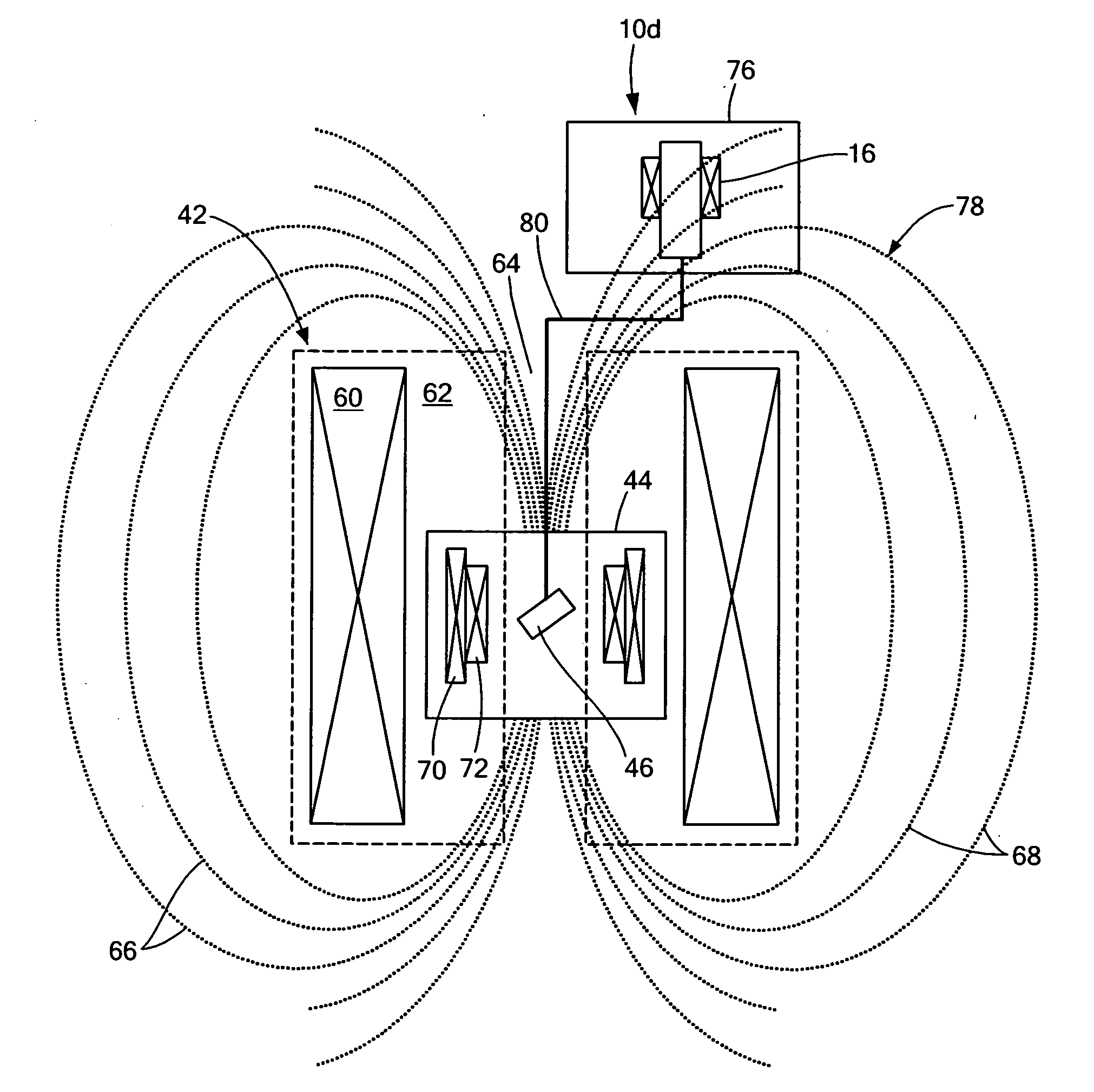
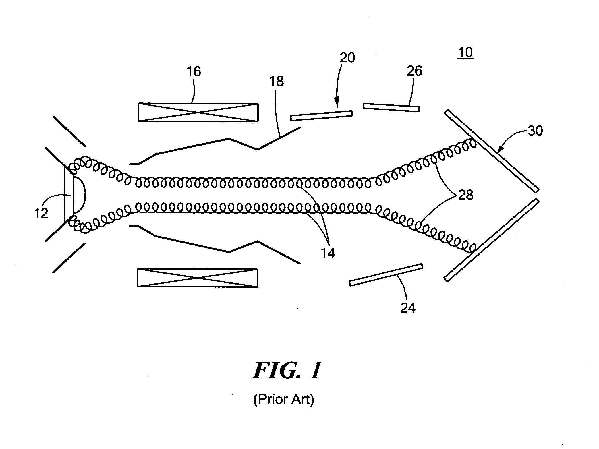
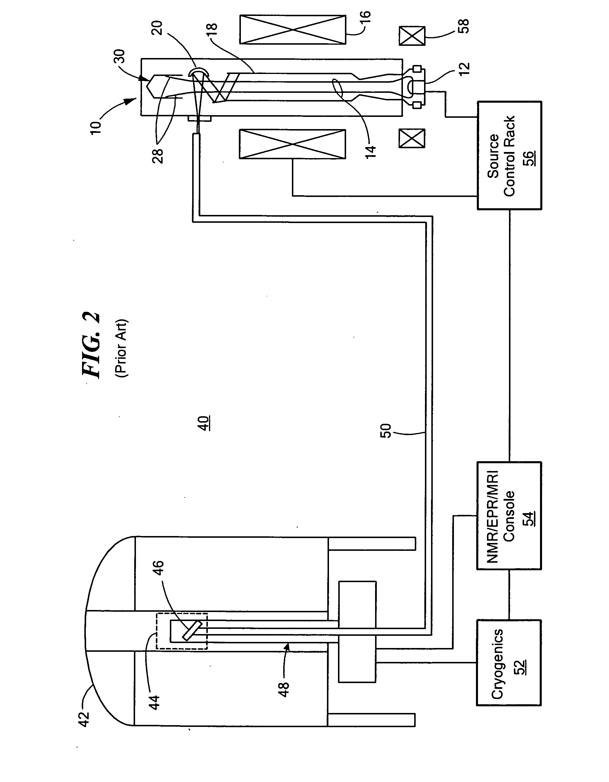
An integrated high-frequency generator system utilizing the magnetic field of the target application including a magnetic resonance magnet having an application zone and a high-frequency (microwave/terahertz) generator zone in the magnetic field of the magnetic resonance magnet; and a high-frequency (microwave/terahertz) generator disposed in the high-frequency (microwave/terahertz) generator zone and utilizing the magnet field of the magnetic resonance magnet to generate the high-frequency (microwave/terahertz) radiation. The magnetic resonance magnet may have an auxiliary magnetic field source for modifying the magnetic field profile in the high-frequency (microwave/terahertz) generator zone. The high-frequency (microwave/terahertz) generator may include an electron gun for generating an electron beam adapted to be focused by a magnetic field source having a spatially rising region, a homogenous region and a decaying region, an interaction structure for generating high-frequency (microwave/terahertz) radiation, an internal mode converter in the homogenous region for extracting the high-frequency (microwave/terahertz) radiation through a window, and a reduced collector disposed substantially in the homogenous region before the electron beam spreads in the decaying region.

Description

FIELD OF THE INVENTION[0001]This invention relates to an integrated high-frequency generator system utilizing the magnetic field of the target application and in one embodiment to such adapted for use in magnetic resonance systems such as a nuclear magnetic resonance (NMR) or magnetic resonance imaging (MRI) system with dynamic nuclear polarization (DNP), or an electron paramagnetic / spin resonance (EPR / ESR) system.BACKGROUND OF THE INVENTION[0002]Microwave and terahertz radiation can be generated either by a solid-state device based on semiconductors, a vacuum electron device (VED) based on the interaction between an electron beam and an electromagnetic circuit or by photonics based sources such as lasers. In the millimeter wave (30-300 GHz) regime VED based sources are dominant because of their high power, wide bandwidth, efficiency and robustness when compared to solid-state and photonics based devices. The aforementioned advantages of VEDs are also valid in the terahertz (300 GHz...

Claims


Application Information

Patent Timeline
IPC IPC(8): G01V3/00
CPCG01R33/282H01J25/025G01R33/3815G01R33/3607G01R33/3873G01R33/3875G01R33/62
Inventor SIRIGIRI, JAGADISHWAR R.MALY, THORSTEN
Owner BRIDGE 12 TECH
Why Eureka
Try Eureka