
Liquid Crystal Display Device

Inactive Publication Date: 2012-07-12
JAPAN DISPLAY INC
View PDF7 Cites 12 Cited by
  • Summary
  • Abstract
  • Description
  • Claims
  • Application Information

AI Technical Summary

Benefits of technology

[0014]The present invention provides a liquid crystal display device equipped with a touch panel such that a terminal portion where a TFT substrate does not overlap with a color filter and that is constructed from a single plate is protected from the outside; and even when a touch panel of a single plate type is used, the device has no problem in connection of the flexible wiring substrate.
[0019]According to the present invention described above, even when the front window is made large to cover and protect the terminal portion of the liquid crystal display panel, and when the touch panel is constructed from a single plate, the PET film do not need to be provided to avoid the contact between the touch panel and the protrusion of the connection portion of the flexible wiring substrate. The process of forming the PET film can be omitted, thereby suppressing increase in the manufacturing cost of the liquid crystal display device.
[0020]Further, reflection at the boundary between the touch panel and the PET film can be prevented to improve image quality. Since the PET film is not used, polarizing effect that would otherwise be caused due to the PET film will not occur. Visibility of the liquid crystal display screen is not obstructed even when polarizing sunglasses are used. Further, since the PET film is not used, the thickness of the liquid crystal display device can be decreased by a portion corresponding to that of the PET film.

Problems solved by technology

When the thickness of the liquid crystal display panel is to be reduced, a problem in physical strength will arise.
If a physical pressure is exerted upon a display surface of a liquid crystal display panel, then the liquid crystal display panel may be damaged.
However, this does not reinforce the terminal portion of the TFT substrate where the physical strength is particularly low.
In spite of the need for protecting the portion where only the TFT substrate exists as a single plate, the device disclosed in JP-A-2003-36143 is not provided with such protection.

Method used


Image

  • Liquid Crystal Display Device
  • Liquid Crystal Display Device
  • Liquid Crystal Display Device

Examples


embodiment 1

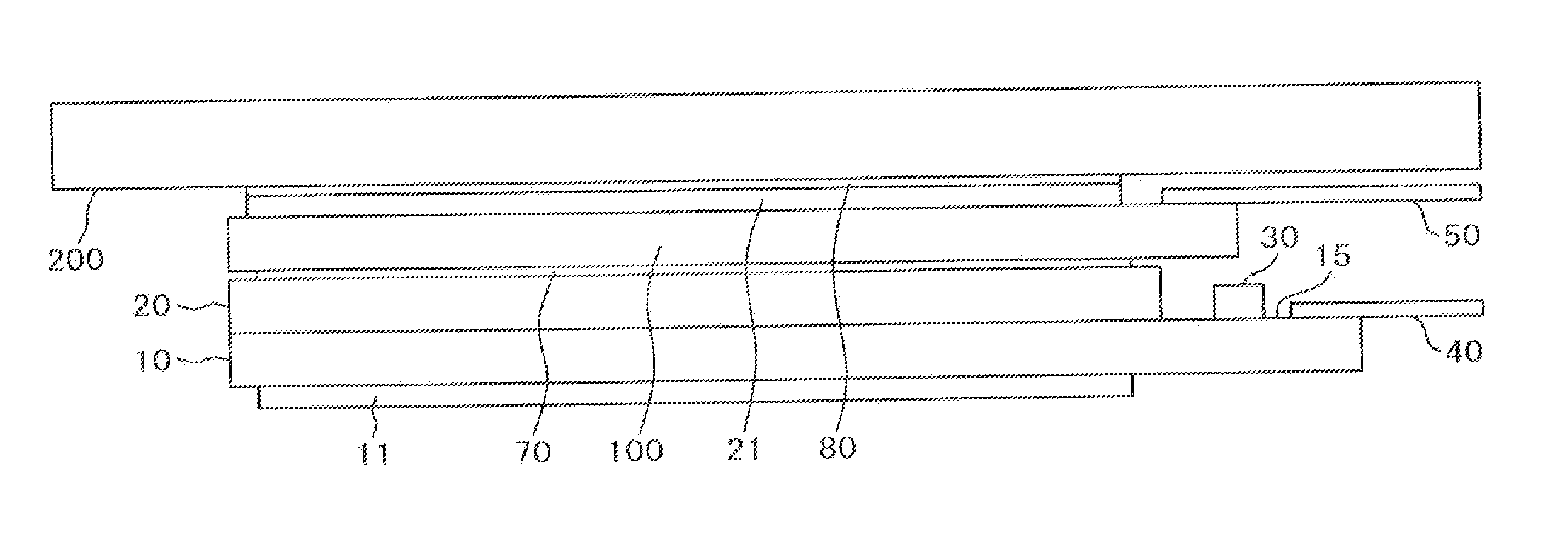
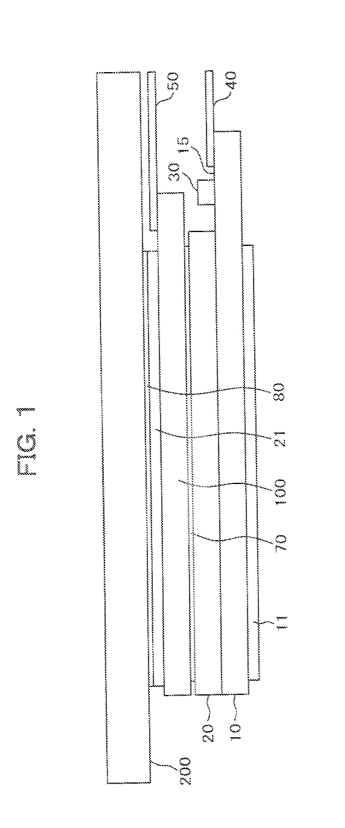
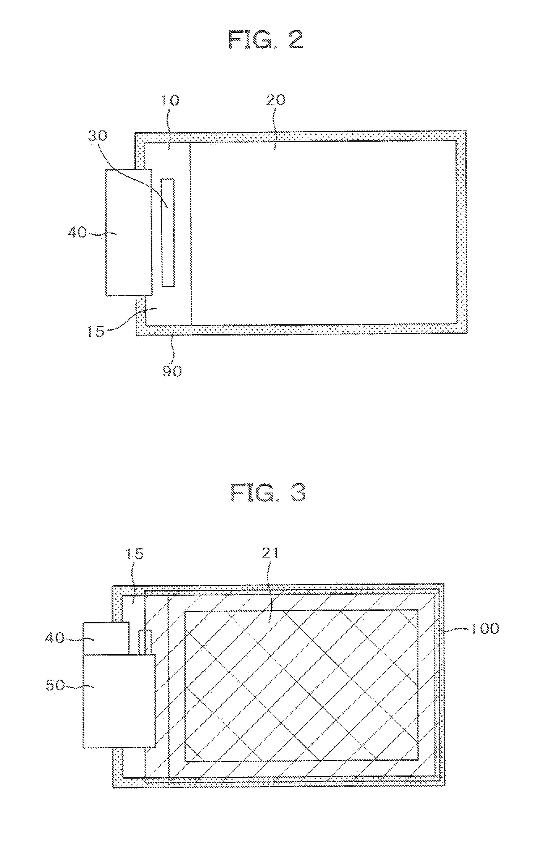
[0039]FIG. 1 is a cross sectional view of a liquid crystal display device according to the present invention. In FIG. 1, a color filter 20 is stacked on a TFT substrate 10. Liquid crystals (not illustrated) are put between the TFT substrate 10 and the color filter substrate 20. A lower polarizing plate 11 is bonded to the lower side of the TFT substrate 10. A backlight (not illustrated) is disposed below the lower polarizing plate 11. Light emitted from the backlight is polarized by the lower polarizing plate 11 and then enters the liquid crystal layer.

[0040]A driving IC 30 is disposed on a terminal portion 15 where the color filter 20 does not overlap with the TFT substrate 10. A main flexible wiring substrate 40 is also attached to the terminal portion 15 to connect the liquid crystal display panel with the outside.

[0041]The portion in which the TFT substrate 10 does not overlap with the color filter substrate 20 is constructed from a single plate of the TFT substrate 10 and its s...


PUM


Abstract

A liquid crystal display device includes a touch panel constructed from a single substrate plate and disposed over a liquid crystal display panel. A color filter is disposed over a TFT substrate, and the touch panel is bonded onto the color filter substrate by way of a first adhesion layer. An upper polarizing plate is bonded over the touch panel, and a front window is bonded over the upper polarizing plate via a second adhesion layer. The front window covers a terminal portion which is a portion where only the TFT substrate exists so as to physically protect the portion. Since the upper polarizing plate is disposed over the touch panel, the connection portion of the flexible wiring substrate for the touch panel does not contact with the front window. Thus, the touch panel can be prevented from being strained.

Description

CLAIM OF PRIORITY[0001]The present application claims priority from Japanese Patent Application JP 2011-004201 filed on Jan. 12, 2011, the content of which is hereby incorporated by reference into this application.BACKGROUND OF THE INVENTION[0002]1. Field of the Invention[0003]The present invention relates to a liquid crystal display device, and particularly relates to a small display device including a touch panel used for cellular phones, etc.[0004]2. Description of the Related Art[0005]A liquid crystal display device includes a TFT substrate, a color filter opposing the TFT substrate, and liquid crystals put between the TFT substrate and the color substrate. The TFT substrate has pixels including pixel electrodes, thin film transistors (TFT), etc. formed thereon in a matrix form. The color filter substrate has color filters, etc. formed at positions corresponding to the pixel electrodes of the TFT substrate. The liquid crystal display device forms images by controlling light tran...

Claims


Application Information

Patent Timeline
IPC IPC(8): G09G3/36G06F3/041
CPCG06F3/041G02F1/133528G02F1/13338G06F2203/04103G06F3/0412G06F3/04164
Inventor OKAZAKI, KENGOARISATO, KOZOKONDO, YASUAKI
Owner JAPAN DISPLAY INC
Learn More