Liquid ejecting head and liquid ejecting apparatus

a liquid ejecting head and liquid ejecting technology, applied in the direction of printing, inking apparatus, etc., can solve the problems of adjacent crosstalk, affecting the durability of the first-level partition, and affecting the durability of the second-level partition, so as to prevent crosstalk from occurring

Inactive Publication Date: 2012-07-12
SEIKO EPSON CORP
View PDF0 Cites 8 Cited by
  • Summary
  • Abstract
  • Description
  • Claims
  • Application Information

AI Technical Summary

Benefits of technology

[0009]It is an advantage of some aspects of the invention to provide a liquid ejecting head an...

Problems solved by technology

Accordingly, what is known as “adjacent crosstalk,” which occurs between adjacent nozzles, is a problem.
However, with the stated configuration, there is a large difference between the thickness of the partitions of the first-level pressure chambers and the thickness of the partitions of the second-level pressure chambers (that is, a large level difference), and thus there is a risk that the partitions of the second-level pressure chambers will interfere when the piezoelectric element and the active surface (that is, a vibrating plate) displace.
On the other hand, in the case where the height of the first-level pressure chamber partitions is increased in order to prevent interference between the piezoelectric elements a...

Method used


Image

  • Liquid ejecting head and liquid ejecting apparatus
  • Liquid ejecting head and liquid ejecting apparatus
  • Liquid ejecting head and liquid ejecting apparatus

Examples


Embodiment Construction

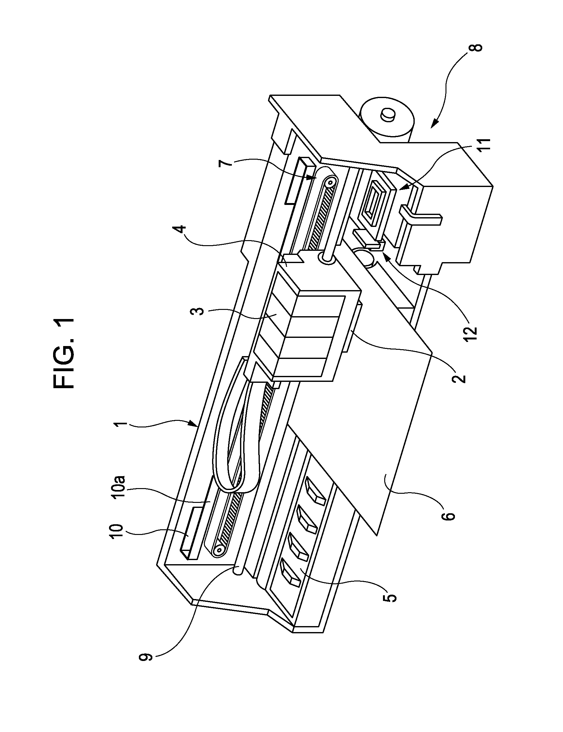
[0019]Hereinafter, an embodiment of the invention will be described with reference to the appended drawings. Although various limitations are made in the embodiment described hereinafter in order to illustrate a specific preferred example of the invention, it should be noted that the scope of the invention is not intended to be limited to this embodiment unless such limitations are explicitly mentioned hereinafter. An ink jet recording apparatus (referred to as a “printer 1”) provided with a recording head 2, which is a type of liquid ejecting head, will be described hereinafter as an example of a liquid ejecting apparatus according to the invention.

[0020]FIG. 1 is a perspective view illustrating the configuration of the printer 1. The printer 1 includes: a carriage 4, to which the recording head 2 is attached, and to and from which ink cartridges 3, which are a type of liquid supply source, can be attached and removed; a platen 5 that is disposed below the recording head 2 during r...


PUM


Abstract

A liquid ejecting head, in which a plurality of pressure chambers that communicate with corresponding nozzles are formed by partitions, that ejects a liquid through the nozzles that communicate with the pressure chambers by causing an active surface (an elastic membrane) that seals an opening surface of the pressure chambers to deform using a piezoelectric element and thus causing the pressure of the liquid within the pressure chambers to fluctuate. The partitions that separate adjacent pressure chambers from each other are formed having a plurality of levels, the plurality being three or more, so that the partitions become thicker from the side on which the active surface is present toward the side on which the nozzles are present.

Description

BACKGROUND[0001]1. Technical Field[0002]The present invention relates to liquid ejecting heads mounted in liquid ejecting apparatuses such as ink jet recording apparatuses and to liquid ejecting apparatuses in which such liquid ejecting heads are mounted, and particularly relates to liquid ejecting heads and liquid ejecting apparatuses that eject a liquid through a nozzle by causing an active surface that configures part of a pressure chamber communicating with the nozzle to displace and causing a fluctuation in the pressure of a liquid within the pressure chamber.[0003]2. Related Art[0004]A liquid ejecting apparatus is an apparatus that includes a liquid ejecting head capable of ejecting a liquid as droplets through a nozzle, and that ejects various types of liquid from this liquid ejecting head. An image recording apparatus such as an ink jet recording apparatus (a printer) that includes an ink jet recording head (called simply a “recording head” hereinafter) and carries out recor...

Claims


Application Information

Patent Timeline
IPC IPC(8): B41J2/145
CPCB41J2/055B41J2202/11B41J2002/14241B41J2/14233
Inventor OTOKITA, KENJI
Owner SEIKO EPSON CORP
Why Eureka
Try Eureka