Optical sensors for use in vital sign monitoring

a technology of optical sensors and vital signs, applied in the field of medical devices for monitoring vital signs, can solve the problems of low probability of being hypoxic, disrupting red/ir(ppg) waveforms, and walking patients typically yielding noisy ppg waveforms, etc., to enhance the accuracy of cnibp measurement, improve signal-to-noise ratio, and accurately extract ac signals

Active Publication Date: 2012-07-12
SOTERA WIRELESS
View PDF10 Cites 202 Cited by
  • Summary
  • Abstract
  • Description
  • Claims
  • Application Information

AI Technical Summary

Benefits of technology

[0017]As described in these applications, the Composite Technique (or, alternatively, the ‘Hybrid Technique’ referred to therein) typically uses a single PPG waveform from the SpO2 measurement (typically the IR(PPG) waveform, as this typically has a better signal-to-noise ratio than the RED(PPG) waveform), along with the ECG waveform, to calculate a parameter called ‘pulse transit time’ (PTT) which strongly correlates to blood pressure. Specifically, the ECG waveform features a sharply peaked QRS complex that indicates depolarization of the heart's left ventricle, and, informally, provides a time-dependent marker of a heart beat. PTT is the time separating the peak of the QRS complex and the onset, or ‘foot’, of the RED / IR(PPG) waveforms; it is typically a few hundred milliseconds. The QRS complex, along with the foot of each pulse in the RED / IR(PPG), can be used to more accurately extract AC signals using a mathematical technique described in detail below. In other embodiments both the RED / IR(PPG) waveforms are collectively processed to enhance the accuracy of the cNIBP measurement.
[0024]In certain embodiments the processing unit features a touchpanel display that renders a first user interface that displays information describing oxygen saturation, a second user interface that displays information describing blood pressure, and a third user interface that displays information describing ECG signals. The processing unit can also include a barcode scanner that scans a barcode of a medical professional (located, e.g., on their badge). In response, the wrist-worn transceiver can render a user interface corresponding to the medical professional. This prevents the patient from viewing medical information that may, for example, cause unnecessary alarm.

Problems solved by technology

For example, the sensor worn on the lower arm (which may be within the wrist-worn transceiver) monitors movement of the patient's hand and fingers; such motion typically disrupts the RED / IR(PPG) waveforms.
For example, a walking patient typically yields noisy PPG waveforms, but also has a low probability of being hypoxic due to their activity state.
Similarly, a patient that is convulsing or falling typically yields noisy RED / IR(PPG) waveforms from which it is difficult to extract an SpO2 value.

Method used


Image

  • Optical sensors for use in vital sign monitoring
  • Optical sensors for use in vital sign monitoring
  • Optical sensors for use in vital sign monitoring

Examples


Embodiment Construction

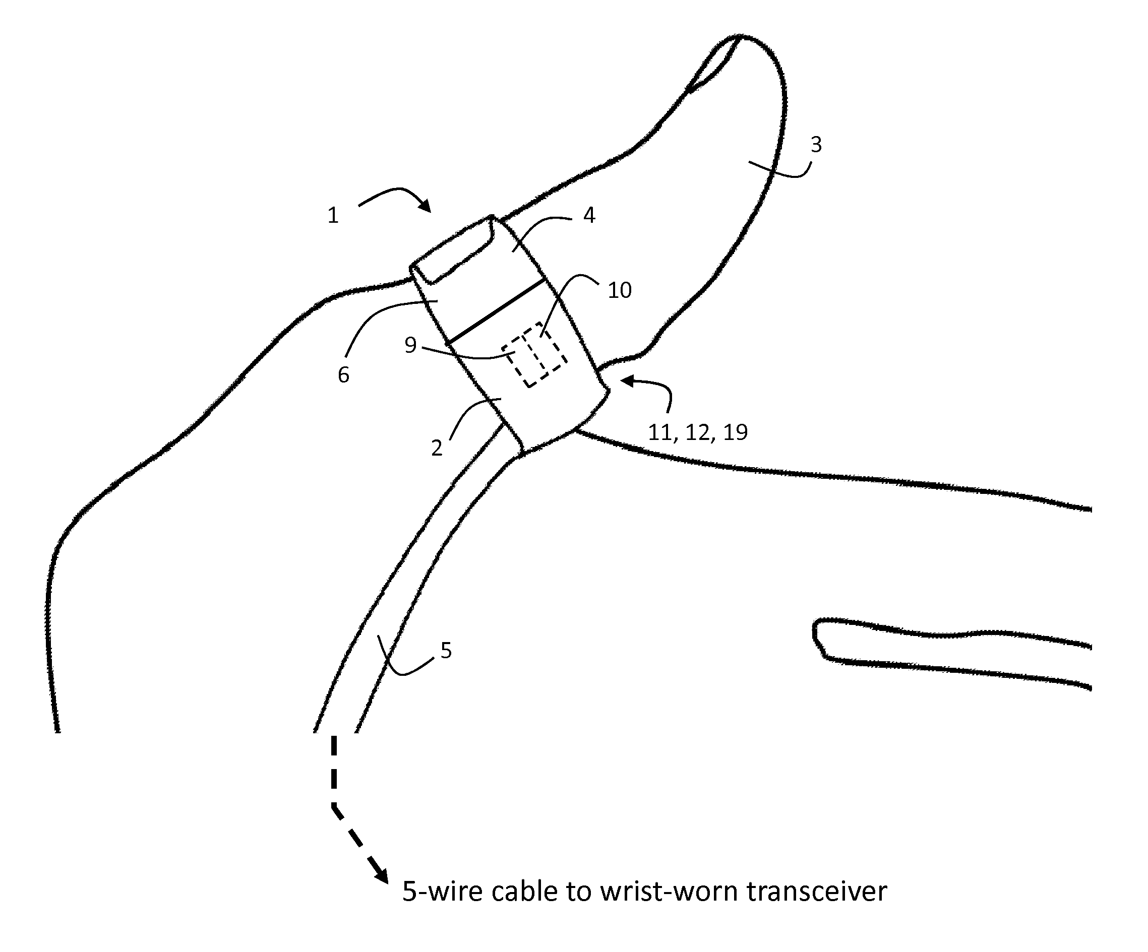
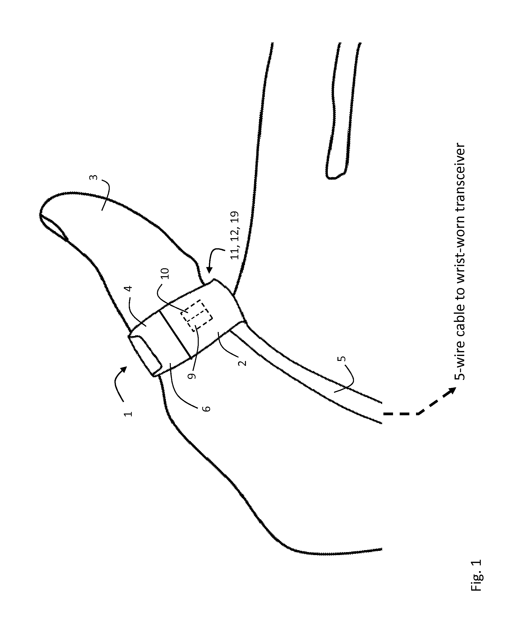
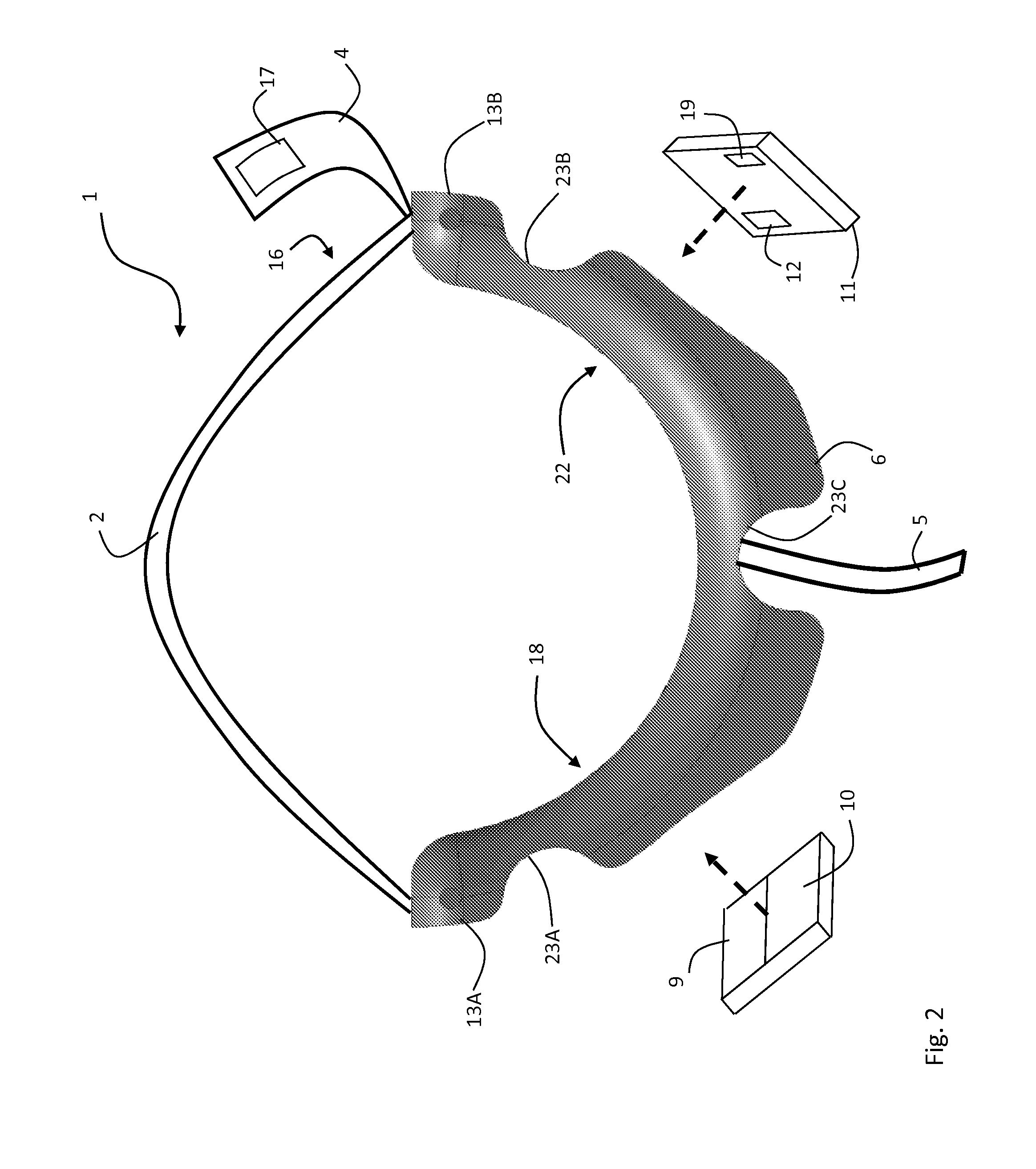
[0060]FIGS. 1 and 2 show a pulse oximeter probe 1 shaped as a finger ring that wraps around a base of patient's thumb 3 to measure SpO2 and cNIBP. The probe 1 is designed to be comfortably worn for extended periods (e.g. several days) while freeing up the patient's thumb and hands for activities such as reading and eating that are commonplace in, e.g., a hospital. Motion corresponding to these and other activities can affect the SpO2 measurement and is detected with a network of accelerometers worn on the patient's body. The probe 1 makes a transmission-mode optical measurement along an inner portion of the thumb 3 with a pair of embedded LEDs 9, 10 operating at, respectively, 660 and 905 nm, and a single photodetector 12 that detects these wavelengths after they pass through vasculature and other tissue lying beneath the LEDs 9,10. Specifically, both LEDs 9, 10 and the photodetector 12 are positioned to measure blood pulsing in portions of the princeps pollicis artery, which is the...


PUM


Abstract

The invention provides a body-worn system that continuously measures pulse oximetry and blood pressure, along with motion, posture, and activity level, from an ambulatory patient. The system features an oximetry probe that comfortably clips to the base of the patient's thumb, thereby freeing up their fingers for conventional activities in a hospital, such as reading and eating. The probe secures to the thumb and measures time-dependent signals corresponding to LEDs operating near 660 and 905 nm. Analog versions of these signals pass through a low-profile cable to a wrist-worn transceiver that encloses a processing unit. Also within the wrist-worn transceiver is an accelerometer, a wireless system that sends information through a network to a remote receiver, e.g. a computer located in a central nursing station.

Description

CROSS REFERENCES TO RELATED APPLICATIONS[0001]This application is a continuation-in-part of U.S. patent application Ser. No. 12 / 171,886, filed Jul. 11, 2008, which claims priority to U.S. Provisional Application No. 60 / 949,052, filed Jul. 11, 2007; and also a continuation-in-part of U.S. patent application Ser. No. 12 / 138,194, filed Jun. 12, 2008, which claims priority to U.S. Provisional Application No. 60 / 943,464, filed Jun. 12, 2007 and U.S. Provisional Application No. 60 / 983,198, filed Oct. 28, 2007; and also a continuation-in-part of U.S. patent application Ser. No. 12 / 487,283, filed Jun. 18, 2009, which claims priority to U.S. Provisional Application No. 61 / 073,681, filed Jun. 18, 2008; and also a continuation-in-part of U.S. patent application Ser. No. 12 / 650,374, filed Dec. 30, 2009, which is a CIP of U.S. patent application Ser. No. 12 / 138,194, filed Jun. 12, 2008, which claims priority to U.S. Provisional Application No. 60 / 943,464, filed Jun. 12, 2007 and U.S. Provisional...

Claims


Application Information

Patent Timeline
Patent Type & Authority Applications(United States)
IPC IPC(8): A61B5/1455A61B5/024A61B5/021
CPCA61B5/0002A61B2560/0468A61B2560/0462A61B2560/0412A61B5/7239A61B5/7225A61B5/7207A61B5/6838A61B5/6826A61B5/14551A61B5/1118A61B5/1117A61B5/1116A61B5/0816A61B5/0408A61B5/0245A61B5/02225A61B5/02055A61B2562/0219A61B5/746A61B5/25
Inventor MOON, JIMMCCOMBIE, DEVINBANET, MATTDHILLON, MARSHAL
Owner SOTERA WIRELESS
Why Eureka
Try Eureka