Projecting project outcome

a project outcome and project technology, applied in the field of projecting project outcome, can solve the problems of reducing the probability of sufficient effects being realized, complex choice, and significant cause and effect complexity, and achieves simple cost and time management, increased suitability of project design, and greater robustness of match

Inactive Publication Date: 2012-07-12
BRM FUSION
View PDF12 Cites 2 Cited by
  • Summary
  • Abstract
  • Description
  • Claims
  • Application Information

AI Technical Summary

Benefits of technology

[0074]Features of the embodiments make it possible to calculate a descriptor that is based on the content and that takes into account the characteristics of the design component, the positioning of the design component in the overall project design and any time periods related to the design component is active for.
[0075]The time period dimension can allow greater robustness of the match of the design component to the performance outcomes to increase the suitability of the project design.
[0076]Broadly, embodiments of the present specification enable complicated project designs to be defined, optimized and realized. Embodim

Problems solved by technology

In situations such as large engineering, computer, organizational and government change projects the complexity of cause and effect is significant.
The complexity of factors to consider decreases the probability of sufficient effects being realized.
This has given rise to highly complex choices and the need for effective ways for creating and managing project designs so they satisfy the performance outcomes and benefits expected.
Typically it is not possible to provide automation of the link between the capabilities expected from a project and the performance outcomes.
For this reason, efficient and quantitative optimization of the trading-off the impact of changes to a

Method used


Image

  • Projecting project outcome
  • Projecting project outcome
  • Projecting project outcome

Examples


Embodiment Construction

[0142]The following detailed description is of the best currently contemplated modes. The description is not to be taken in a limiting sense, but is made merely for the purpose of illustrating the general principles, and the scope of the invention is defined only by the appended claims and their equivalents.

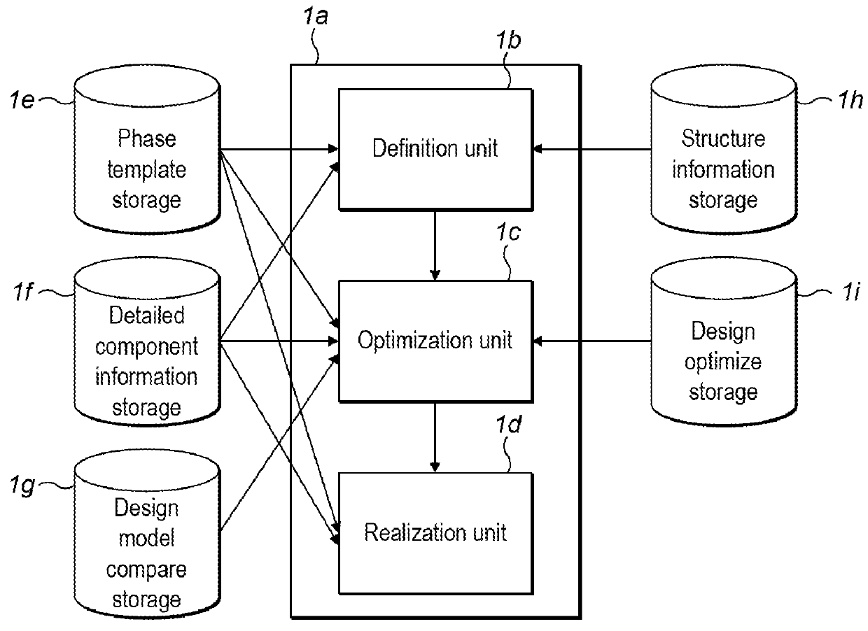
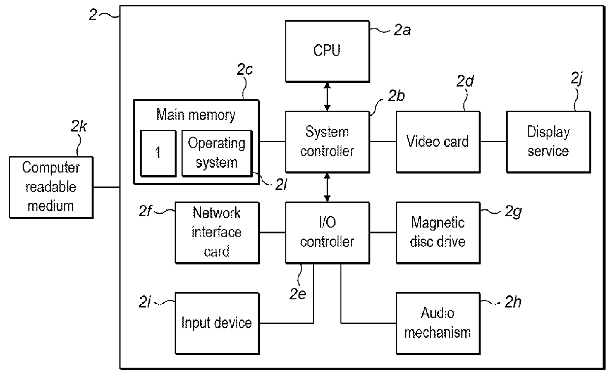
[0143]Embodiments herein provide a software application, also referred to herein as a program that is usable by a user, such as a project planner or project manager to assist them in project design and project execution. The software is executed on computing apparatus, which may be a general purpose computer.

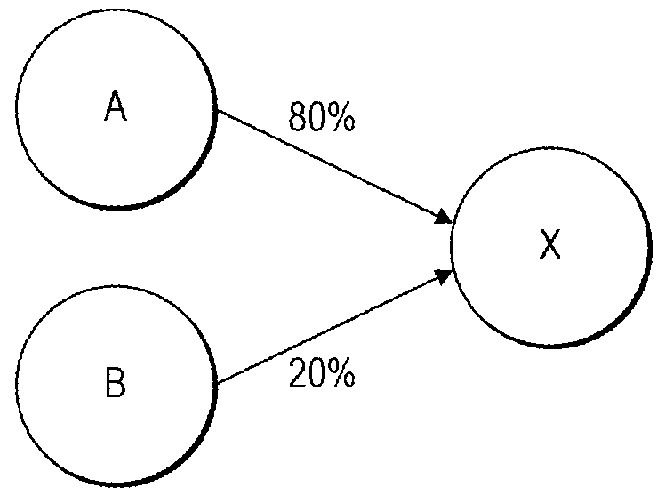
[0144]As a program the user is presented with a GUI that allows them to define a project with all the required components. The components enable a project design and consist of those representing causes, effects and supporting elements. Components are defined and optimized in a manner that the impact on the performance outcomes can be measured. Put succinctly, the software pr...


PUM


Abstract

Apparatus has at least one processor and at least one memory having computer-readable code stored thereon which when executed controls the at least one processor to perform a method comprising: providing a graphical user interface (GUI); allowing a user to define, through the GUI, a project at least in terms of plural initiative components, plural outcome components, and interrelationships between the initiative components and the outcome components; allowing the user to define, through the GUI, two or more quality components for each initiative component, each quality component comprising a performance level and resource costs associated with achieving the performance level; allowing the user to define, through the GUI, plural parameters associated with the project, the parameters including performance levels and resource costs for each of at least two quality components; allowing the user to allocate, through the GUI, resources to each of the initiative components; providing a projected measure of project outcome based on the allocated resources; allowing the user to alter, through the GUI, the resources allocated to the initiative components; and providing revised projected measure of project outcome based on the altered resource allocations.

Description

CROSS-REFERENCE TO RELATED APPLICATIONS[0001]The current application claims priority to Great Britain Application No. GB 1100215.1, filed Jan. 7, 2011, the disclosure of which is incorporated herein by reference.FIELD OF THE INVENTION[0002]The present specification relates to projecting project outcome. In particular, although not exclusively, the specification relates to increasing the understanding, choice and management of interventions (causes) so as to maximize the value of the resultant effects.BACKGROUND OF THE INVENTION[0003]To efficiently and effectively design and manage a project, a business case, a design or investment proposal or the like (hereinbelow, simply referred to as a project) a system and management method for agreeing the performance outcomes and benefits expected (effects) and what interventions are best to achieve them that are at an acceptable cost is required.[0004]For example, when a person learns to drive a car there are common effects expected such as a...

Claims


Application Information

Patent Timeline
IPC IPC(8): G06F3/048
CPCG06Q10/06G06Q10/04
Inventor HOWES, TREVORSISSONS, BEN
Owner BRM FUSION
Why Eureka
Try Eureka