Overflow Valve For Prevention Of Water Vapor Loss

a technology of overflow valve and water vapor, which is applied in the direction of valve actuation float, machine/engine, light and heating apparatus, etc., can solve the problems of excessive water loss, large height change, and large arm devices

Inactive Publication Date: 2012-07-19
APRICUS SOLAR
View PDF23 Cites 10 Cited by
  • Summary
  • Abstract
  • Description
  • Claims
  • Application Information

AI Technical Summary

Benefits of technology

[0013]The present invention overcomes the drawbacks of the prior art by allowing the valve to open when the water level rises above the level of the bottom of the drain member port. Objectives of the present invention include allowing a valve to open once the water height exceeds the bottom of the drain member, allowing for unrestricted water flow through the drain member.

Problems solved by technology

It is desirable to allow water to exit the tank to prevent excess water from accumulating in the tank, as the excess water can overflow out the top of the tank, may lose temperature quickly, and may cause corrosion problems, as the water may leak and / or cause the tank to rust.
These float arm devices are large and require a large height change in water for the ball to rise enough to in turn fully open or close the valve.
This may lead to the valve being left open for longer than desired and may cause excessive water to be lost, including water vapor loss.
As water vapor is at a higher temperature than its corresponding liquid (it is in the vapor state, which is a higher energy than a liquid state), excess loss of water vapor and energy results in heat loss from the tank that decreases the overall efficiency of the hot water storage device.
In the case of a non-pressurized tank, a fully sealed valve may not be desirable when there are no other means of exposure to the outside atmosphere.
However, the lever has a groove, which is always open, such that water vapor from the tank will exit the tank and cause the overall efficiency of the tank to not be maximized.
Furthermore, the '307 patent suffers from being large and requiring a large height change in the water.
Other designs that have been used for water level overflow control employ an electromagnetic valve, which adds cost and complexity to the system.
Electromagnetic valves require an electrical supply to operate correctly, resulting in additional energy consumption and decreasing the overall efficiency of the hot water storage system.
In the aforementioned prior art patents, the problem of preventing excessive water from being lost, including water vapor loss, is not solved.
Moreover, the prior art does not solve the problem of designing a valve that quickly, accurately and reliably opens to allow water to exit the drain port once water reaches a certain level, which is small, simple and has a low cost.

Method used


Image

  • Overflow Valve For Prevention Of Water Vapor Loss
  • Overflow Valve For Prevention Of Water Vapor Loss
  • Overflow Valve For Prevention Of Water Vapor Loss

Examples


Embodiment Construction

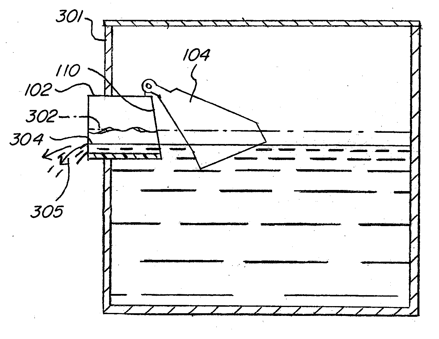
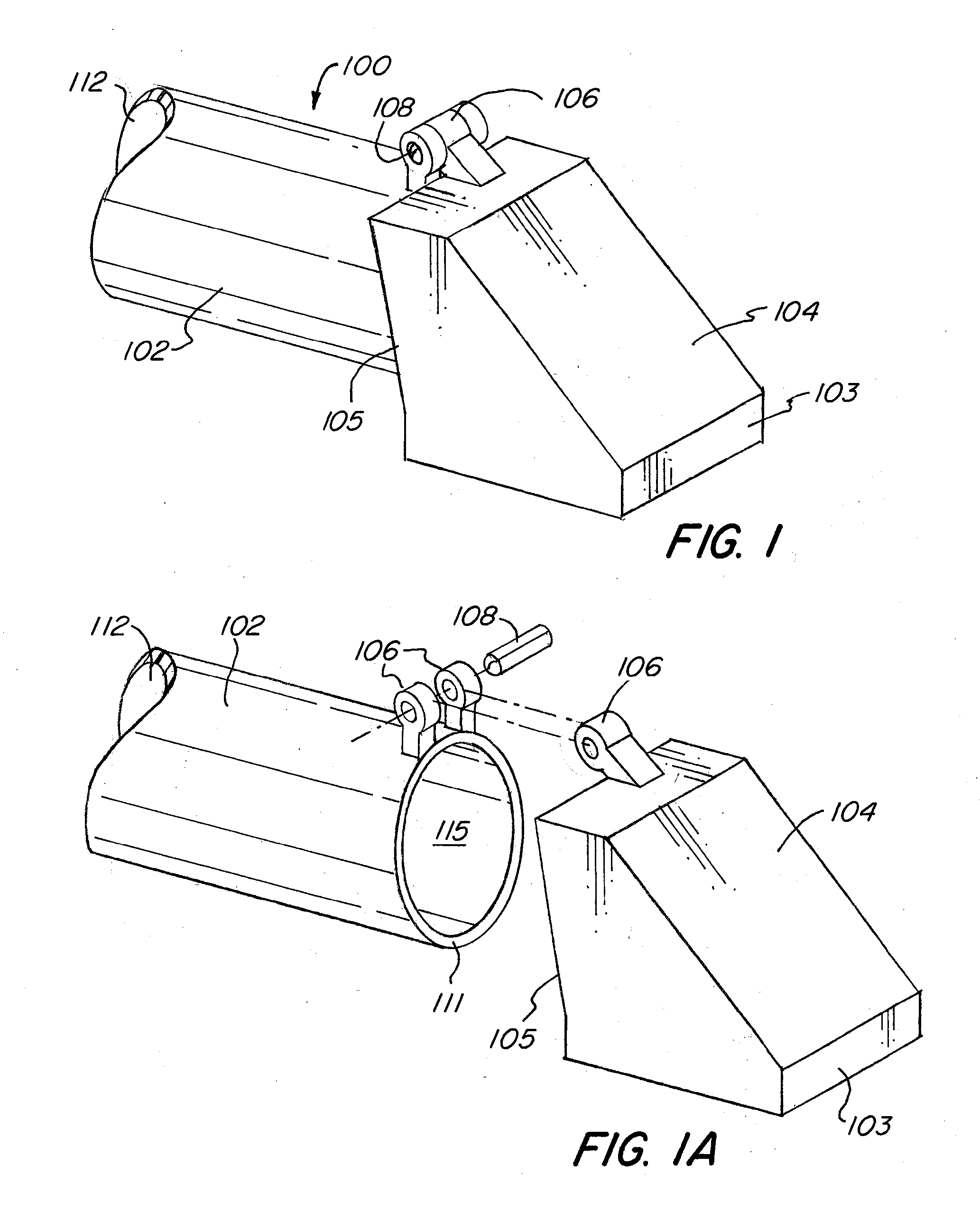
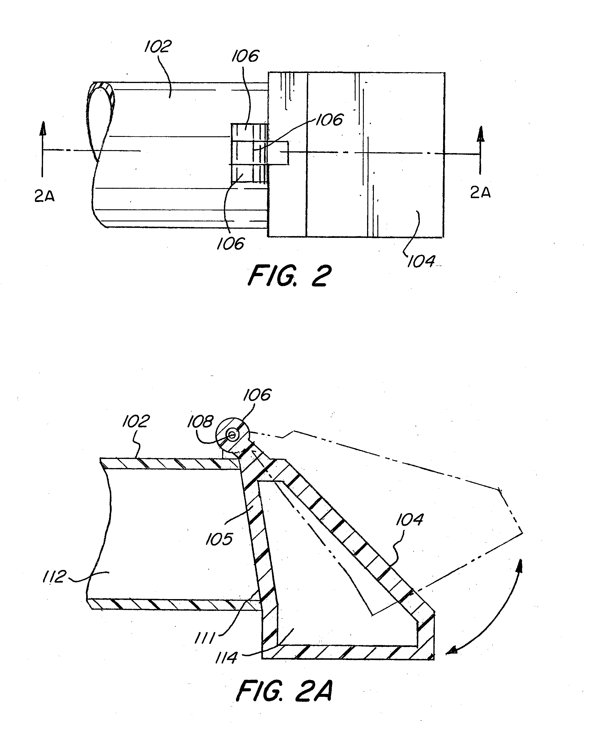
[0040]FIG. 1 shows an assembled view of valve of an embodiment of the present invention. FIG. 1A shows an exploded view of the valve of FIG. 1. FIG. 1 provides head member 104 and rotatable member 106 / 108. The rotatable member 106 / 108 may be manufactured and fused into the head member or may be manufactured as a separate element from the head member 104. FIG. 1 also provides a drain member 102. When closed, the head member 104 rests on the drain member 102, closing the overflow valve and reducing vapor loss.

[0041]More specifically, head member 104 has a proximal end 103 and a distal end 105. The drain member 102 has a proximal end 111 and a distal end 112. As shown, the distal end of the head member 105 rests on the proximal end of the drain member 111. In certain embodiments, the distal end of the drain member 111 (also known as a drain port), is tapered, so that the distal end of the head member 105 rests on the proximal end of the drain member 111. In other embodiments, the drain...


PUM


Abstract

A system and valve for regulating the level of a fluid. The valve having a floating head member that is connected via a rotatable member to a drain member, where fluid may drain from the valve. The system having the valve and a tank, where the fluid drains from the tank once the fluid level reaches the level of the drain member of the valve.

Description

FIELD OF THE INVENTION[0001]The present invention relates to a valve for regulating the level of a fluid and for prevention of water vapor loss from a multi-purpose water storage tank.BACKGROUND OF THE INVENTION[0002]Hot water storage tanks are used to provide and circulate hot water throughout a plumbing system. Hot water storage tanks may include a port at a designated height on the tank to allow for excess water to exit the tank. It is desirable to allow water to exit the tank to prevent excess water from accumulating in the tank, as the excess water can overflow out the top of the tank, may lose temperature quickly, and may cause corrosion problems, as the water may leak and / or cause the tank to rust.[0003]Valves currently used for water level overflow control typically employ a large float arm that is attached to a valve. When the water level rises, the float rises, causing the arm to rotate. This rotation causes the valve to open and allows water to escape the tank. These floa...

Claims


Application Information

Patent Timeline
Patent Type & Authority Applications(United States)
IPC IPC(8): F15D1/00F16K1/16
CPCF16K1/20F16K33/00Y02E60/142F28D2020/0065F28D20/0034Y10T137/7323Y10T137/7485Y10T137/8593Y02E60/14
Inventor HUMPHREYS, MICHAEL
Owner APRICUS SOLAR
Why Eureka
Try Eureka