Permanent magnet rotor of motor

Active Publication Date: 2012-07-19
ZHONGSHAN BROAD OCEAN MOTOR MFG
View PDF9 Cites 20 Cited by
  • Summary
  • Abstract
  • Description
  • Claims
  • Application Information

AI Technical Summary

Benefits of technology

[0006]In view of the above-described problems, it is one objective of the invention to provide a permanent magnet rotor of a motor that has a simple structure, excellent manufacturability in terms of production and assembly, low manufacturing costs, excellent electromagnetic performance, and meanwhile it is robust enough to avoid potential deformation.

Problems solved by technology

Although magnetic short circuits are reduced by magnetic circuit saturation, they cannot be completely eliminated.
For further reasons that the narrower edge is more preferred to avoid the magnetic short circuits, rotor laminations are difficult to be made, the narrow edge 21 is likely to deform to make it difficult for the tegular magnet to be inserted in the groove, and moreover the tegular magnet needs to be finely finished before being inserted in the groove; if the groove is too small, the tegular magnet cannot be inserted; if the groove is too big, a gap would occur, leading to the increased magnetic pressure drop, therefore the manufacturability is poor, the assembly speed is slow, product quality is hardly to be guaranteed, and the electromagnetic performance is unsatisfactory.

Method used


Image

  • Permanent magnet rotor of motor
  • Permanent magnet rotor of motor
  • Permanent magnet rotor of motor

Examples


example 1

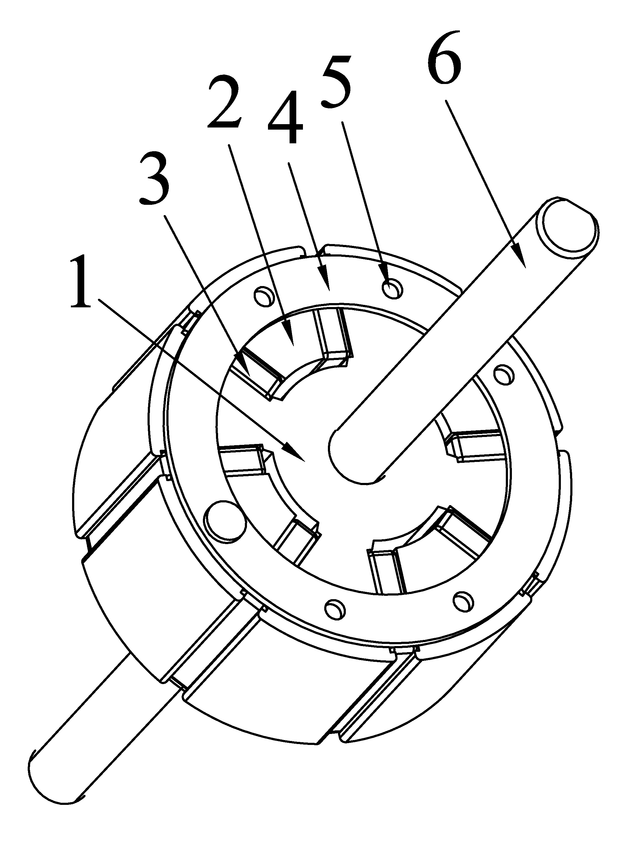
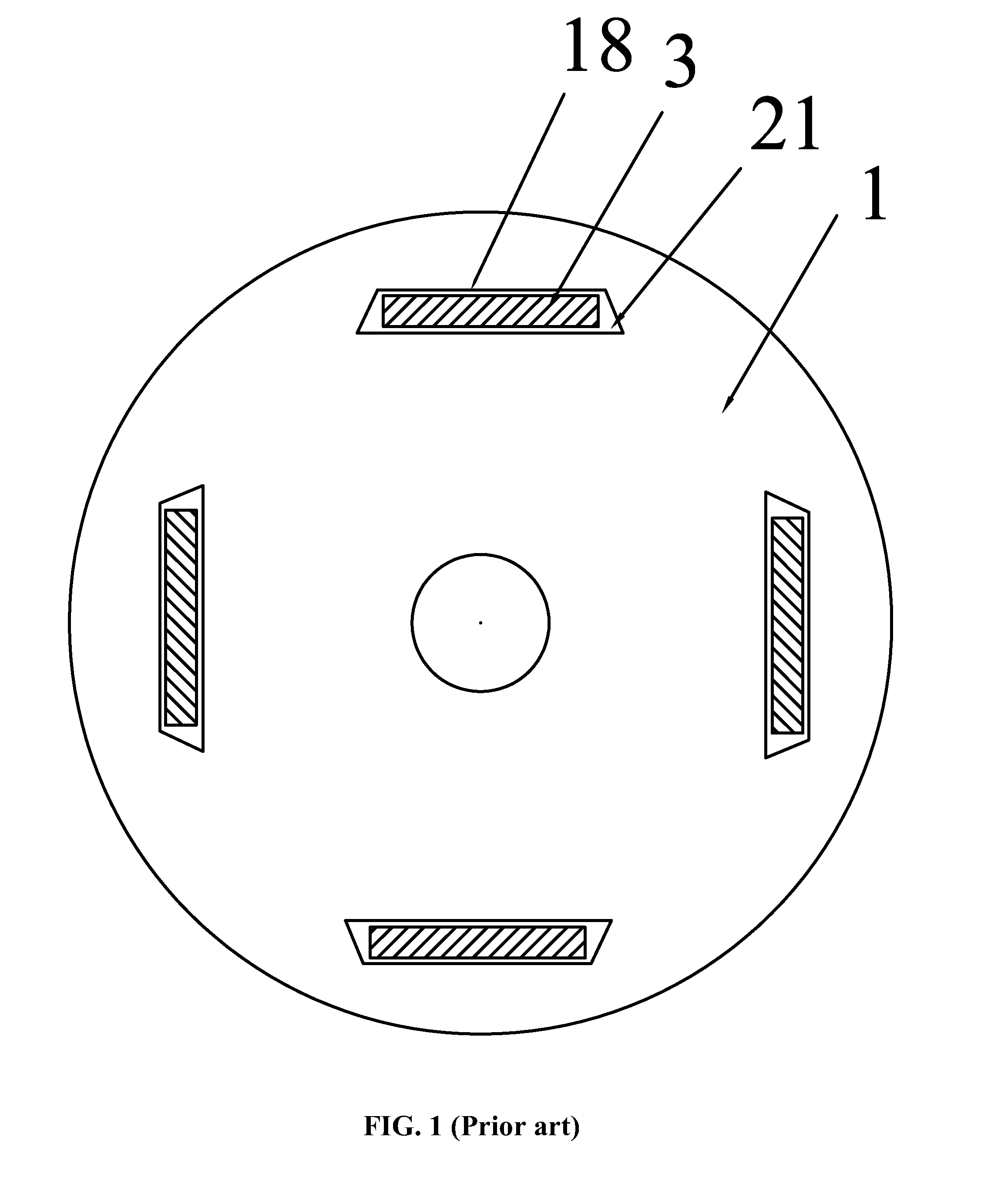
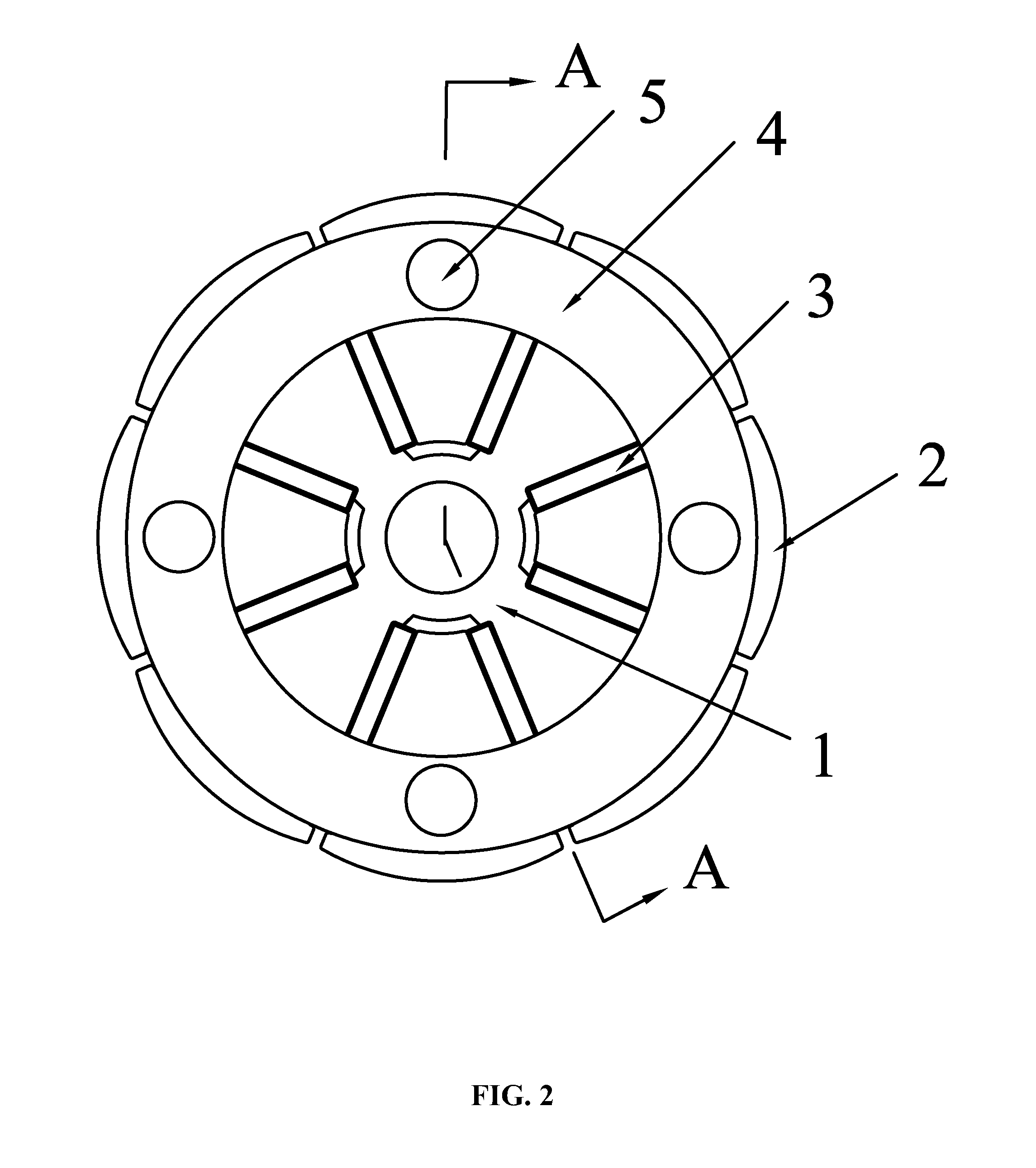
[0041]As shown in FIGS. 1-9, a permanent magnet rotor of a motor comprises a rotor core and permanent magnets 3, in which the permanent magnets 3 are embedded in the rotor core. The rotor core comprises a central core 1, a plurality of sectional cores 2, and a connecting mechanism. The sectional cores 2 are integrated with the central core 1 via the connecting mechanism to form a whole iron core. Each permanent magnet 3 is clamped in a groove 18 formed between each sectional core 2 and the central core 1. A plurality of grooves 18 and the permanent magnets 3 are distributed in the radial direction and the grooves 18 are evenly distributed along the circumference of the rotor. The central core 1 comprises an annular central seat 11 and a plurality of fixed core blocks 12 extending therefrom. A cavity 13 is formed between two adjacent fixed core blocks 12 with each sectional core 2 embedded therein. The grooves 18 are formed between each sectional core 2 and each fixed core block 12 f...

example 2

[0042]Following Example 1 except that the rotating shaft 6 is coupled with the annular central seat 11 via a damping device. The damping device comprises pins 8 and a shock ring 9. The rotating shaft 6 is sheathed with an inner core 7 and the inner core 7 is embedded in the bore 16 inside the annular central seat 11. A gap 10 is formed between the inner core 7 and the annular central seat 11. On the outer surface of the inner core 7 and at the corresponding position on the inner wall of the bore 16 are disposed with a plurality of recesses 101, and the shock ring 9 is embedded in the gap 10 and the recesses 101. The shock ring 9 in the recesses 101 are disposed with bores, and the pins 8 are embedded in the bores. The damping device disposed between the rotating shaft and the stator core can effectively reduce vibration to enable the rotor to work stably.

[0043]The rotor core used in the invention comprises a central core 1, a plurality of sectional cores 2 and a connecting mechanism...


PUM


Abstract

A permanent magnet rotor of a motor including a rotor core and permanent magnets. The rotor core includes a central core, a plurality of sectional cores, and a connecting mechanism. The sectional cores are integrated with the central core via the connecting mechanism to form a whole iron core. Grooves are formed between each sectional core and the central core and the permanent magnets are embedded in the grooves. The permanent magnet rotor has a simple structure, excellent manufacturability in terms of production and assembly, low manufacturing costs, excellent electromagnetic performance, and meanwhile is robust enough to avoid potential deformation.

Description

CROSS-REFERENCE TO RELATED APPLICATIONS[0001]This application is a continuation of International Patent Application No. PCT / CN2010 / 077259 with an international filing date of Sep. 25, 2010, designating the United States, now pending, and further claims foreign priority benefits to Chinese Patent Application No. 200910214416.2 filed Dec. 25, 2009. The contents of all of the aforementioned applications, including any intervening amendments thereto, are incorporated herein by reference.BACKGROUND OF THE INVENTION[0002]1. Field of the Invention[0003]The invention relates to a permanent magnet rotor of a motor.[0004]2. Description of the Related Art[0005]As shown in FIG. 1, grooves 18 are usually disposed in an iron core 1 to hold tegular magnets for a conventional permanent magnet rotor and a narrow edge 21 is disposed at the two ends of each groove 18 and at the rotor periphery. Although magnetic short circuits are reduced by magnetic circuit saturation, they cannot be completely elimi...

Claims


Application Information

Patent Timeline
IPC IPC(8): H02K1/27
CPCH02K1/30H02K1/2773
Inventor PAN, MINGPAN
Owner ZHONGSHAN BROAD OCEAN MOTOR MFG
Why Eureka
Try Eureka