Multiple capacitive (button) sensor with reduced pinout

Active Publication Date: 2012-07-19
SEMTECH CORP
View PDF3 Cites 5 Cited by
  • Summary
  • Abstract
  • Description
  • Claims
  • Application Information

AI Technical Summary

Benefits of technology

[0014]In some embodiments of a touch sensor in accordance with the present invention, the bias driver circuit is configured such that when the LED drivers are disabled and the capacitive sensors are enabled, the b

Problems solved by technology

However, the single sensor controller solution still requires one I/O port per fun

Method used


Image

  • Multiple capacitive (button) sensor with reduced pinout
  • Multiple capacitive (button) sensor with reduced pinout
  • Multiple capacitive (button) sensor with reduced pinout

Examples


Example

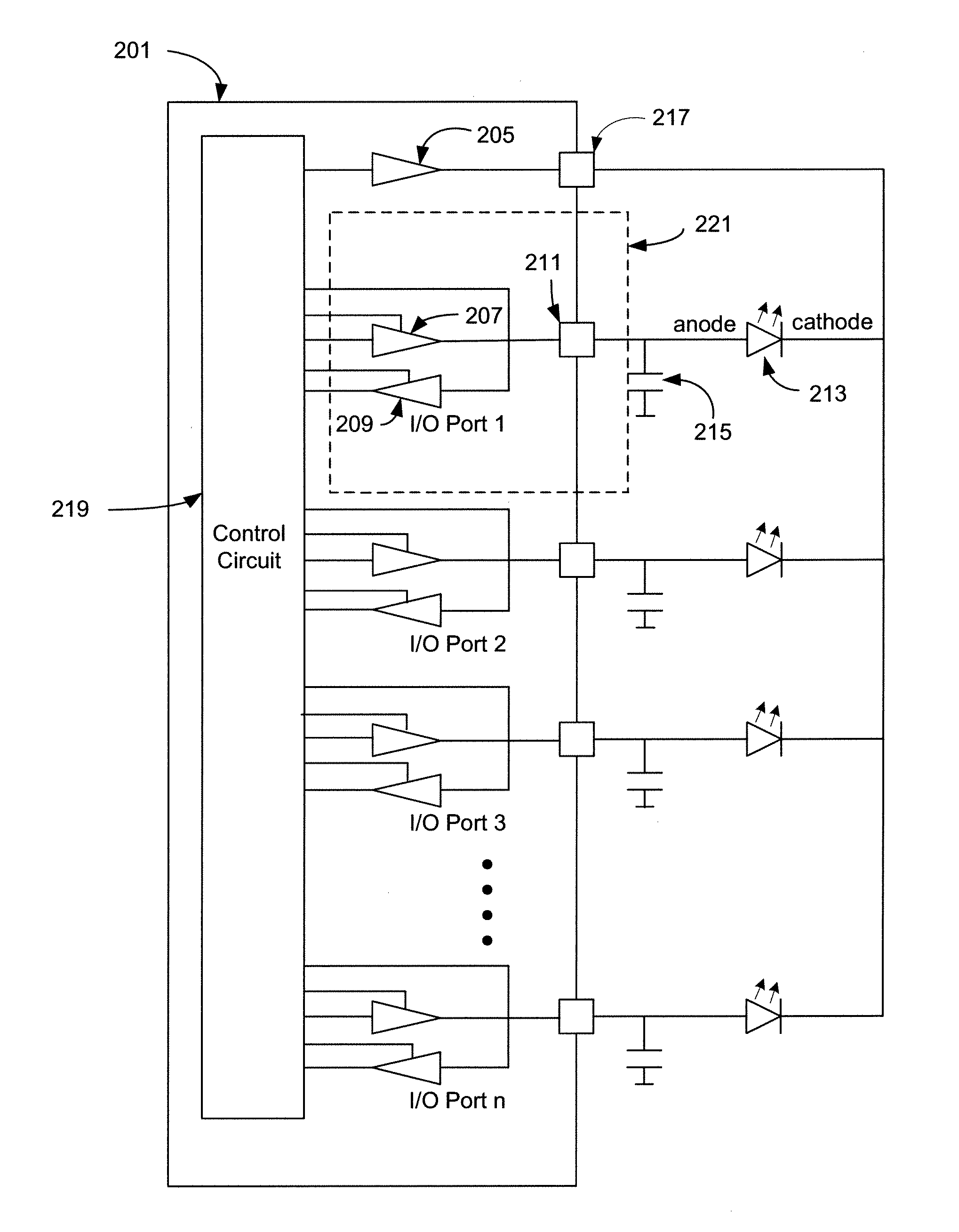
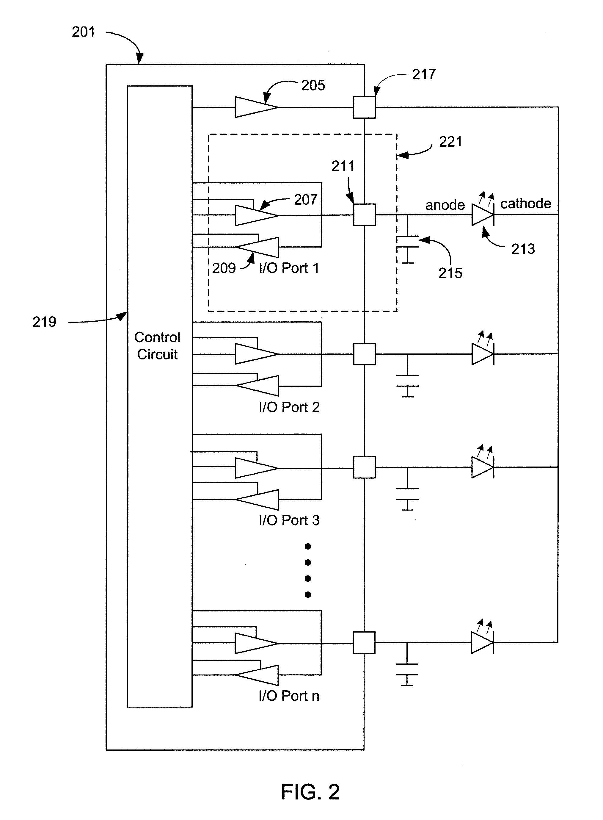
[0022]An embodiment of the present invention includes an apparatus and method of using a single I / O port as a capacitive input and LED driver. FIG. 2 depicts a simplified circuit diagram of a multiple-touch-sensor controller 201 in accordance with an embodiment of the present invention. The multiple-touch-sensor controller 201 contains a bias driver 205, a control circuit 219 and n number of I / O ports 221. Each I / O port 221 contains both an LED driver 207 and a capacitive sensor 209. The output of LED driver 207 is connected to the input of capacitive sensor 209 and pad 211. Pad 211 is further connected to control circuit 219, capacitive element 215 and the anode of LED 213. The cathode of LED 213 is then connected to bias driver 205 through pad 217. Control circuit 219 controls the LED drivers, capacitive sensors and bias driver based on the functionality needed, as described below.

[0023]FIG. 3 depicts a simplified representation of an I / O port during LED drive operation in accorda...


PUM


Abstract

A capacitive touch sensor and LED driver device achieves a reduction in pin count by multiplexing LED drive functionality and capacitive sense functionality on each input/output pin. A control circuit switches between LED drive mode and capacitive sense mode at a frequency of approximately 200 Hz, although other switching frequencies can be used. A bias driver functions as a current sink for LEDs in LED drive mode and can also be used to drive a bias voltage to the LEDs during capacitive sense mode to improve noise immunity.

Description

RELATED APPLICATION DATA[0001]This application claims priority pursuant to 35 U.S.C. §119(e) to U.S. provisional patent application Ser. No. 61 / 434,321 filed Jan. 19, 2011, the subject matter of which is incorporated by reference herein in its entirety.BACKGROUND OF THE INVENTION[0002]1. Field of the Invention[0003]The present invention relates to multiple-capacitive-sensor controllers, and more particularly, to multiple-capacitive-sensor controllers containing general purpose input-output ports that can be shared by an LED driver and a capacitive touch detector.[0004]2. Description of Related Art[0005]Multiple-capacitive-sensor controllers are well known in the art and are an integral part of a sensor that uses the properties of capacitors to detect physical distance from the user or touches by the user. In addition to being a pure sense device, most multiple-capacitive-sensor controllers also contain input-output ports that can be used to control Light Emitting Diodes (LED).[0006]...

Claims


Application Information

Patent Timeline
IPC IPC(8): H05B37/02
CPCH05B37/0227H03K17/9622H03K2217/960785H05B47/115Y02B20/40G06F3/044
Inventor MONNEY, PASCAL
Owner SEMTECH CORP
Why Eureka
Try Eureka