Mixer monitoring

a technology for monitoring mixers and mixers, applied in the field of mixer monitoring, can solve the problems of no monitoring or only simple, insensitive monitoring of mixers, and achieve the effect of simple control and monitoring

Inactive Publication Date: 2012-07-19
ROBERT BOSCH GMBH
View PDF8 Cites 3 Cited by
  • Summary
  • Abstract
  • Description
  • Claims
  • Application Information

AI Technical Summary

Benefits of technology

[0013]According to another specific embodiment of the method, during a first time interval the high-frequency signal has a first amplitude which is constant over time, and during a second time interval has a second amplitude which is constant over time. The mixer is assessed as functional if the direct-current voltage component of the baseband signal in the second time interval has a different value than in the first time interval. In this specific embodiment, the method may advantageously be carried out even more easily.
[0014]An electronic circuit system according to the present invention includes a mixer for mixing a high-frequency signal and a high-frequency comparison signal, and for outputting a baseband signal. A device is provided for modifying the amplitude of the high-frequency signal as a function of time. An analysis circuit is also provided for assessing the functionality of the mixer based on a comparison of a change in a direct-current voltage component of the baseband signal over time with the change in the amplitude of the high-frequency signal over time. The circuit system is advantageously suited for checking the functionality of passive and active mixers. The circuit system is EMC-compliant and allows simple control and monitoring.

Problems solved by technology

However, in the related art either no monitoring, or only simple, insensitive monitoring, of the mixers is used.

Method used


Image

  • Mixer monitoring
  • Mixer monitoring

Examples


Embodiment Construction

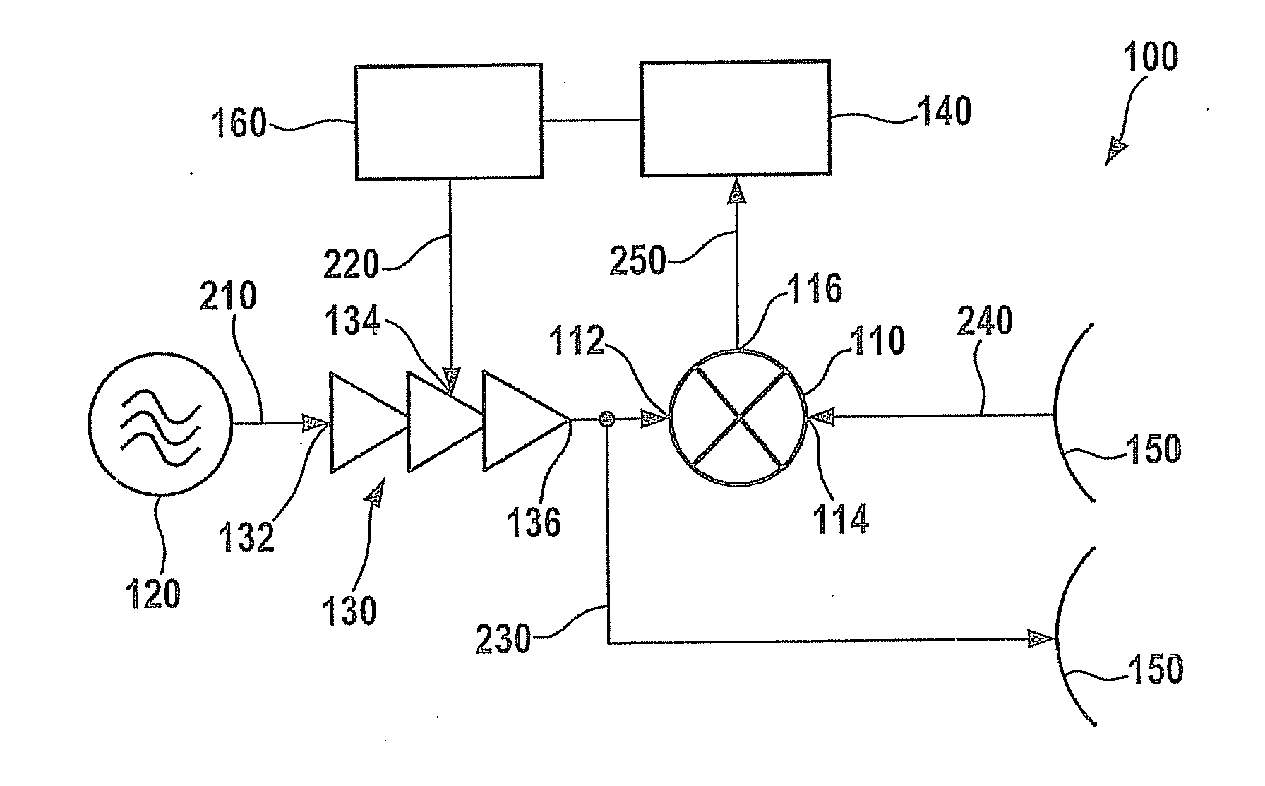
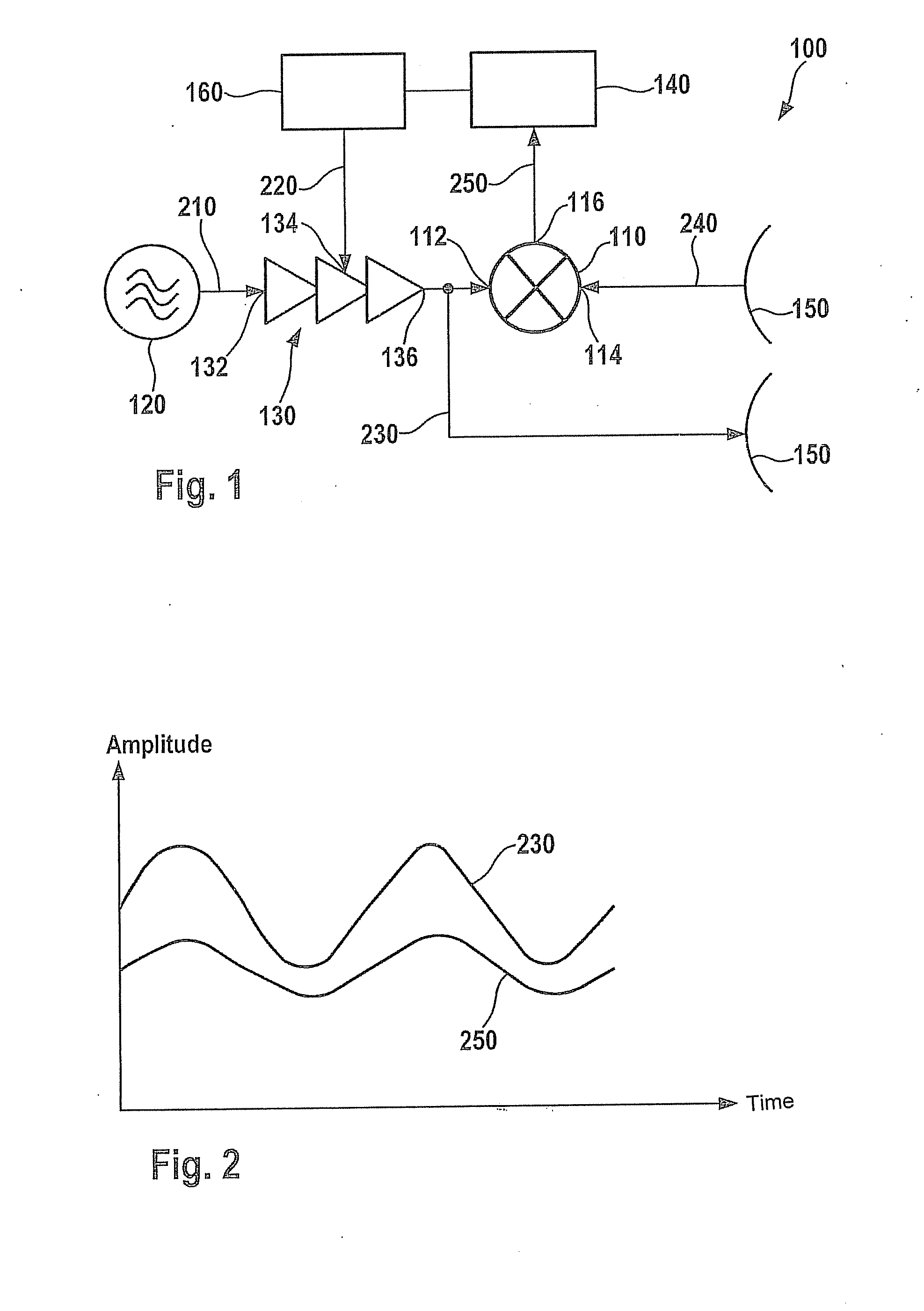
[0019]FIG. 1 shows a schematic illustration of a radar system 100. Radar system 100 may be a frequency-modulated continuous-wave radar, for example. Radar system 100 may be used, for example, for adaptive cruise control in a motor vehicle.

[0020]Radar system 100 has a voltage-controlled oscillator 120. The voltage-controlled oscillator is used for generating a high-frequency signal 210. High-frequency signal 210 may have a frequency in the range of 77 GHz, for example. The voltage-controlled oscillator preferably allows setting of the frequency of high-frequency signal 210. Instead of voltage-controlled oscillator 120, another component may be used for generating high-frequency signal 210.

[0021]Radar system 100 also includes an amplifier 130 having an adjustable gain factor. Amplifier 130 has an amplifier input 132, a modulation input 134, and an amplifier output 136. Amplifier input 132 is connected to voltage-controlled oscillator 120, and receives high-frequency signal 210. Modula...


PUM


Abstract

In a method for checking the functionality of a mixer, the mixer is supplied with a high-frequency signal and a high-frequency comparison signal in order to generate a baseband signal. The amplitude of the high-frequency signal is modified as a function of time. A direct-current voltage component of the baseband signal which is output by the mixer is analyzed to determine the functionality of the mixer.

Description

BACKGROUND OF THE INVENTION[0001]1. Field of the Invention[0002]The present invention relates to a method for checking the functionality of a mixer, and an electronic circuit system.[0003]2. Description of Related Art[0004]Microwave mixers are used in radar systems to mix a high-frequency transmission signal with a received reflection signal, thus obtaining a baseband signal having a lower frequency but which still has the same information content as the reflection signal. It is necessary to monitor the mixer function in safety-relevant systems. However, in the related art either no monitoring, or only simple, insensitive monitoring, of the mixers is used.BRIEF SUMMARY OF THE INVENTION[0005]An object of the present invention is to provide a method for checking the functionality of a mixer. Moreover, another object of the present invention is to provide an electronic circuit system for checking the functionality of a mixer.[0006]In a method according to the present invention for chec...

Claims


Application Information

Patent Timeline
Patent Type & Authority Applications(United States)
IPC IPC(8): G01S7/40
CPCG01S7/35G01S7/4021G01S2007/406G01S7/4056H03D2200/0045G01S7/406G01S7/4069
Inventor HIMMELSTOSS, ARMINCHABAUD, MAIJA
Owner ROBERT BOSCH GMBH
Why Eureka
Try Eureka