Carbon nanotube devices and method of fabricating the same

a technology of carbon nanotubes and carbon nanotubes, which is applied in the field of radio frequency devices, can solve the problems of not having commercially viable electronic applications of nanotube technology availabl

Active Publication Date: 2012-07-19
NORTHROP GRUMMAN SYST CORP
View PDF4 Cites 18 Cited by
  • Summary
  • Abstract
  • Description
  • Claims
  • Application Information

AI Technical Summary

Problems solved by technology

However, no commercially viable electronic applications for n

Method used


Image

  • Carbon nanotube devices and method of fabricating the same
  • Carbon nanotube devices and method of fabricating the same
  • Carbon nanotube devices and method of fabricating the same

Examples


Embodiment Construction

[0028]While the present invention may be embodied in many different forms, a number of illustrative embodiments are described herein with the understanding that the present disclosure is to be considered as providing examples of the principles of the invention and such examples are not intended to limit the invention to preferred embodiments described herein and / or illustrated herein.

[0029]Carbon nanotubes may be fabricated by a variety of methods. The most significant type of carbon nanotube is the single walled nanotube (SWNT). SWNTs can currently be grown up to 10 mm in length and can have either metallic or semiconductor characteristics. That is, depending on orientation of a carbon nanotube's crystal walls, carbon nanotubes may take on metallic characteristics or semiconductor characteristics. Carbon nanotubes (CNT) are referenced throughout this document as either metallic CNTs or semiconductor CNTs to reflect their characteristics.

[0030]Semiconductor CNTs may be selectively d...


PUM


Abstract

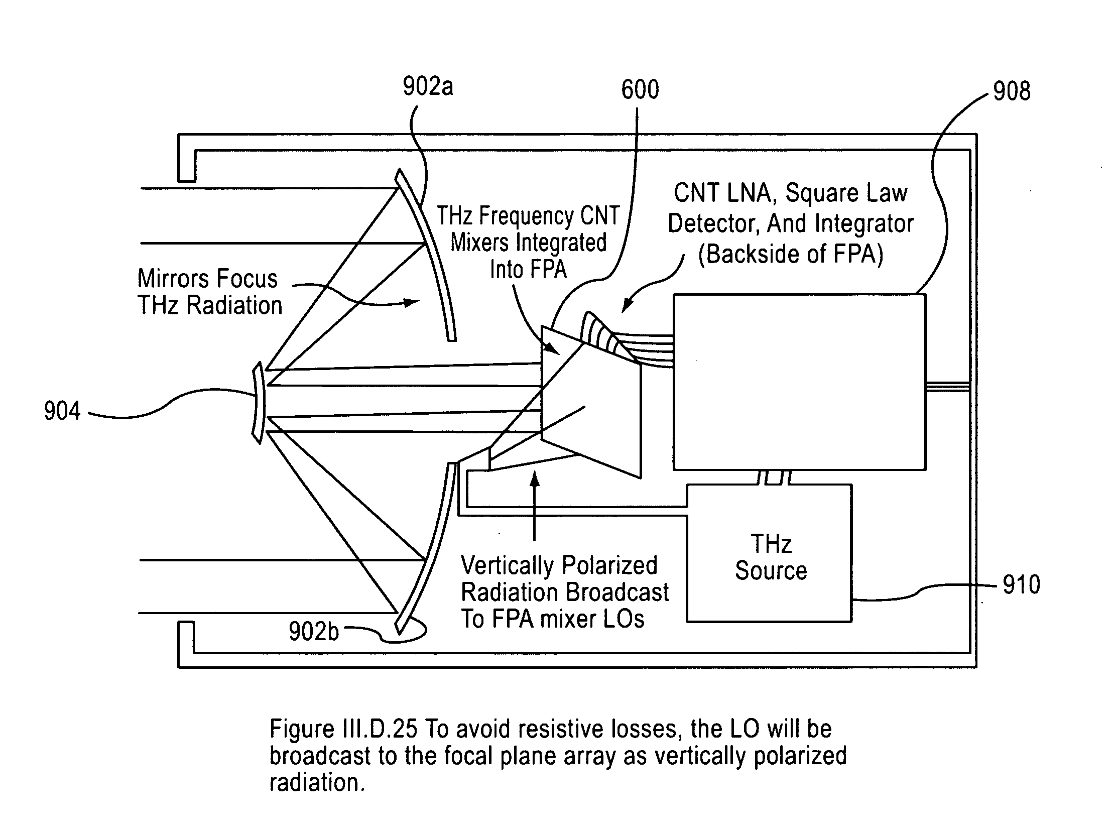
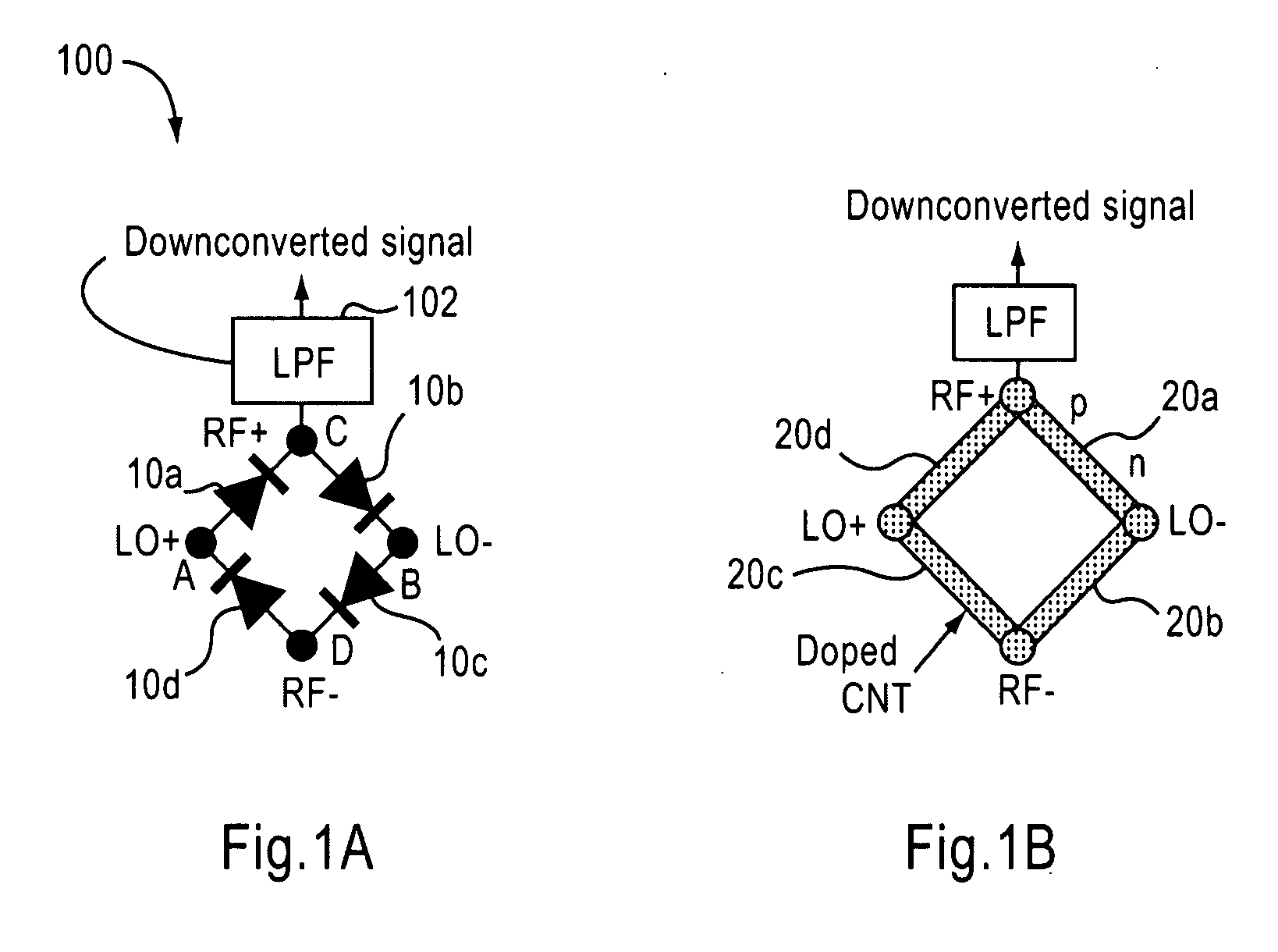
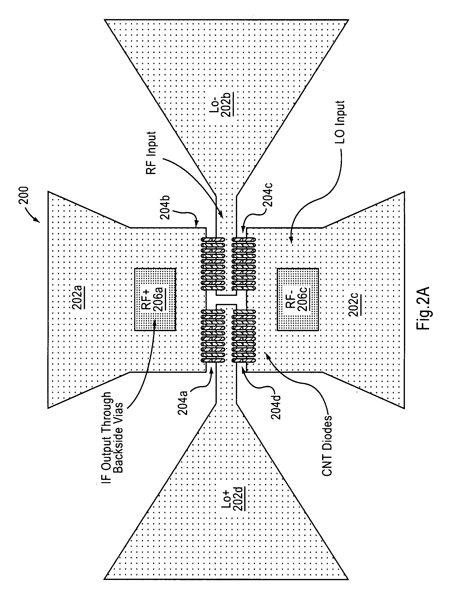
An imaging system includes an RF source, a focal plane array and device for focusing the RF signal from the RF source. The focal plane array includes a plurality of carbon nanotube mixers for capturing RF signals and down-converting the signals to a selected bandwidth and output an output signal. The device focuses the RF signal output from said RF source onto the focal plane array.

Description

RELATED APPLICATION DATA[0001]This application is a continuation-in-part of and claims the benefit of priority to U.S. patent application Ser. No. 11 / 012,864, filed on Dec. 16, 2004, the entire contents of which are hereby incorporated by reference.BACKGROUND OF THE INVENTION[0002]1. Field of the Invention[0003]The present invention relates generally to radio frequency (RF) devices, and more particularly, the present invention relates to high frequency detectors, mixers and scanners that utilize carbon nanotube technology.[0004]2. Description of the Related Art[0005]Carbon nanotubes were discovered in the early 1990s as a product of arc-evaporation synthesis of fullerenes. Scientists have since determined that carbon nanotubes have extraordinary physical characteristics, and their potential use in many different applications has attracted much attention. For example, single-wall carbon nanotubes have high-current density and low capacitance characteristics. However, no commercially ...

Claims


Application Information

Patent Timeline
IPC IPC(8): G01S13/89G01S13/00
CPCG01N21/3581H04B1/28H03D7/02
Inventor PESETSKI, AARON A.ZHANG, HONGPRZYBYSZ, JOHN XAVIERADAM, JOHN DOUGLAS
Owner NORTHROP GRUMMAN SYST CORP
Why Eureka
Try Eureka