High isolation signal routing assembly for full duplex communication

a signal routing and duplex communication technology, applied in the field of wireless transceivers, can solve the problems of system performance degradation, channel to channel isolation improvement, and portion of incident signal leakage, and achieve high isolation and high isolation.

Active Publication Date: 2012-07-19
KNOX MICHAEL E DR
View PDF2 Cites 18 Cited by
  • Summary
  • Abstract
  • Description
  • Claims
  • Application Information

AI Technical Summary

Benefits of technology

[0011]It is an object of the present invention to provide a two way duplex wireless communication signal routing assembly wherein the channel to the channel isolation is improved over prior art arrangements. In particular, the present invention relates to a signal routing assembly, a full duplex transceiver routing assembly and a full duplex transceiver routing assembly including carrier modulation. The signal routing assembly provides high isolation between two separate transmission signal paths utilizing a common port and typically configured to provide high isolation in the direction from the transmit channel transmission path to the receive channel transmission path in a full duplex system. The signal routing assembly allows the two transmission paths to operate using the same carrier frequencies. The signal routing assembly also allows the two transmission paths to operate using different transmit and receive frequencies. In an advantageous application the two different frequencies are close in frequency and are therefore inadequately filtered using a duplexing filter.

Problems solved by technology

It is known that the operation of a local receiver during the time that a local transmitter is transmitting creates receiver problems as the transmitter energy leaks, couples and / or reflects into the receiver resulting in corruption, distortion, saturation and / or desensitization within the receiver.
Depending on the isolation performance of the circulator or coupler, the system performance may degrade when a portion of the transmitted energy leaks into the receiver.
In practice, a portion of the incident signal leaks or couples to the isolated port.
This undesired coupled signal 8 may reduce the performance of the receiver 11.
In some full duplex systems, such as passive UHF RFID systems, this additional loss in received energy does not create difficulties when recovering the received information as these systems are generally forward link limited.
Problems may occur when a portion of the incident transmitter signal couples or leaks into the receiver through the directional coupler which in turn may reduce receiver performance.
Therefore undesired receiver desensitization may occur when signals leak from the local transmitter into the local receiver.
It is well known in industry, that fabricating a circulator with very high isolation (>30 dB) is often difficult and expensive.
A typical junction circulator may have 20 dB isolation resulting in 1% of the transmit energy leaking into the receiver channel.
This leakage signal may greatly affect the performance of the receiver in a full duplex system.
This level of undesired signal would typically saturate and / or desensitize a low power mixer placed in the front end of the receiver.

Method used


Image

  • High isolation signal routing assembly for full duplex communication
  • High isolation signal routing assembly for full duplex communication
  • High isolation signal routing assembly for full duplex communication

Examples


Embodiment Construction

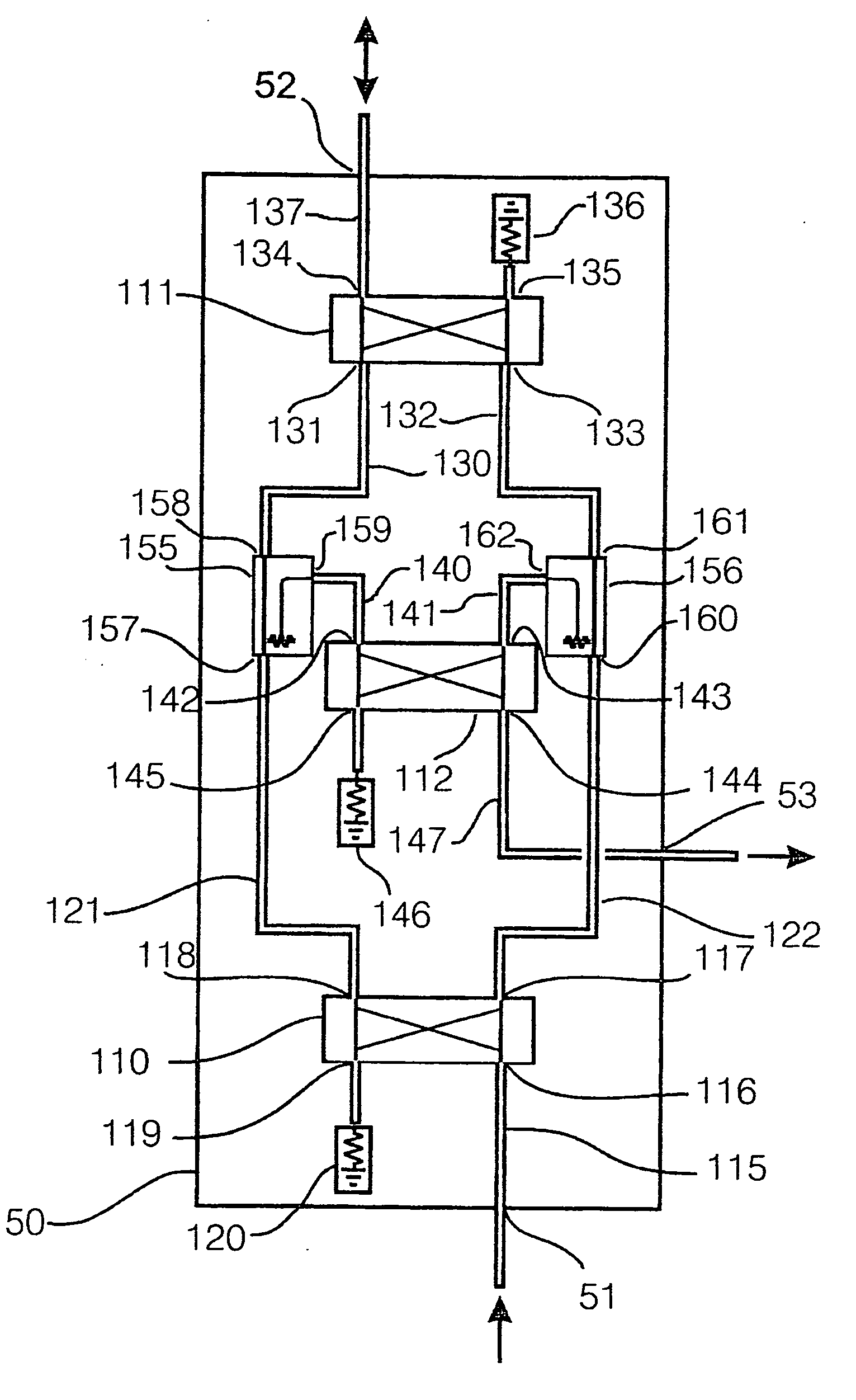
[0058]Improvements in transmit to receive isolation for three-port signal routing devices can be provided using a combination of signal dividers with the proper signal phasing and conventional three port components that when properly connected will combine signals at the desired ports and cancel signals at the isolated ports.

[0059]The generalized construction of the three port signal routing device is shown in FIG. 4. The routing device 50 has one input port 51, one common port 52 and one output port 53. The input signal is received at the input port 51 and routed to the input 59 of a signal divider 54. Input port 51 is typically connected to the local transmitter. Signal divider 54 divides the transmission signal into first and second divided transmission signals output at ports 60 and 61 and having substantially equal amplitudes and a first relative phase shift therebetween. The signal divider 54 is any of a quadrature hybrid, or an equal phase power splitter, e.g., a Wilkinson po...


PUM


Abstract

A signal routing assembly accepts a first transmission signal at an input and outputs a substantial portion of the signal at a common port of the signal routing assembly. A second transmission signal is received at the common port and is routed through the signal routing assembly delivered to output of the signal routing assembly. Leakage signals from routing devices leaking the first transmission signal are terminated inside the signal routing assembly. Leakage signal from a divider/combiner are cancelled by reflect signal from at least one reflector device. A transmitter produces the first transmission signal and the signal routing assembly delivers this signal to the common port of the signal routing assembly. In full duplex operation, second transmission signals received at the common port are routed to the output to be applied to a receiver.

Description

RELATED APPLICATIONS[0001]This application is a continuation-in-part of application Ser. No. 12 / 459,242, filed Jun. 29, 2009, which is a continuation-in-part of international application PCT / US2007 / 026459, filed Dec. 29, 2007 which claims priority to U.S. provisional application 60 / 877,995, filed Dec. 29, 2006, and each of said applications is herein incorporated by reference.TECHNICAL FIELD[0002]The present invention relates to wireless transceivers that operate in full duplex mode providing the simultaneous transmission and reception of radio signals. In particular, but not exclusively, the present invention relates to wireless transceivers that are provided with a means to isolate signals transmitted by the transmitter of the wireless transceiver and received by a receiver of the wireless transceiver.BACKGROUND OF THE INVENTION[0003]Modern wireless communication, radar and radio frequency identification (RFID) systems often operate under full duplex operation. A wireless transcei...

Claims


Application Information

Patent Timeline
Patent Type & Authority Applications(United States)
IPC IPC(8): H04L5/14
CPCH04L12/40013H04L5/14H04B1/44H04L12/66
Inventor KNOX, MICHAEL E.
Owner KNOX MICHAEL E DR
Why Eureka
Try Eureka