
Roller Zipper Slide

Inactive Publication Date: 2012-07-26
WANG LIEN CHOU
View PDF11 Cites 3 Cited by
  • Summary
  • Abstract
  • Description
  • Claims
  • Application Information

AI Technical Summary

Benefits of technology

[0005]The present invention has been accomplished under the circumstances in view. It is the main object of the present invention to provide a roller zipper slide for zip fastener, which improves sliding mobility, reduces zipper teeth wear and prolongs zipper slide lifespan.
[0006]To achieve this and other objects of the present invention, a roller zipper slide includes a slide body having a longitudinal slot on a top slide body block in communication with an internal chamber thereof and two coupling grooves located at two opposite lateral sides of the longitudinal slot, a roller pivotally having two pivot pins respectively pivotally coupled to the coupling grooves and a bottom side thereof projecting into the internal chamber of the slide body right above the engaging position between the left and right series of teen of the zip fastener, thereby improving sliding mobility, reducing zipper teeth wear and prolonging zipper slide lifespan.
[0007]Thus, when the left series of teeth and right series of teeth of the zip fastener that are separated by a center block of the slide body enter the inside of the roller zipper slide, the bottom side of the roller that projects vertically downwardly into the internal chamber of the roller zipper slide right above the engaging position between the left and right series of teen of the zip fastener is kept in contact with the interlocking teeth of the zip fastener, preventing teeth damage due to biasing of the pull tab in a particular angle.
[0008]Further, during sliding movement of the zipper slide to close or open the left and right series of teen of the zip fastener, the roller is rotated relative to and kept in contact with the topmost edges of the protruding upper faces of the left and right series of teeth, minimizing friction resistance, enhancing sliding mobility and prolonging zip fastener's lifespan.
[0009]Further, when the roller is moved to the head end or tail end of the zip fastener, the bottom side of the roller is kept in contact with the teeth of the zip fastener, minimizing surface friction and heat generation and preventing teeth damage due to biasing of the pull tab in a particular angle.

Problems solved by technology

Further, if the protruding upper faces of the left and right series of teeth are not kept in horizontal during interlocking, the teeth may be not interlocked positively.
However, because different zip fastener manufacturers provide different specifications of zip fastener component parts, all commercial zip fastener components are not interchangeable.
However, when the zipper slide of a zip fastener used in a bag or tent is moved to the head end or tail end, biasing of the pull tab in a particular angle may cause the zipper slide to rub against the interlocking teeth or zipper tapes, causing a zipper tooth or zipper tape damage and shortening the lifespan of the zip fastener,

Method used


Image

  • Roller Zipper Slide
  • Roller Zipper Slide
  • Roller Zipper Slide

Examples


Embodiment Construction

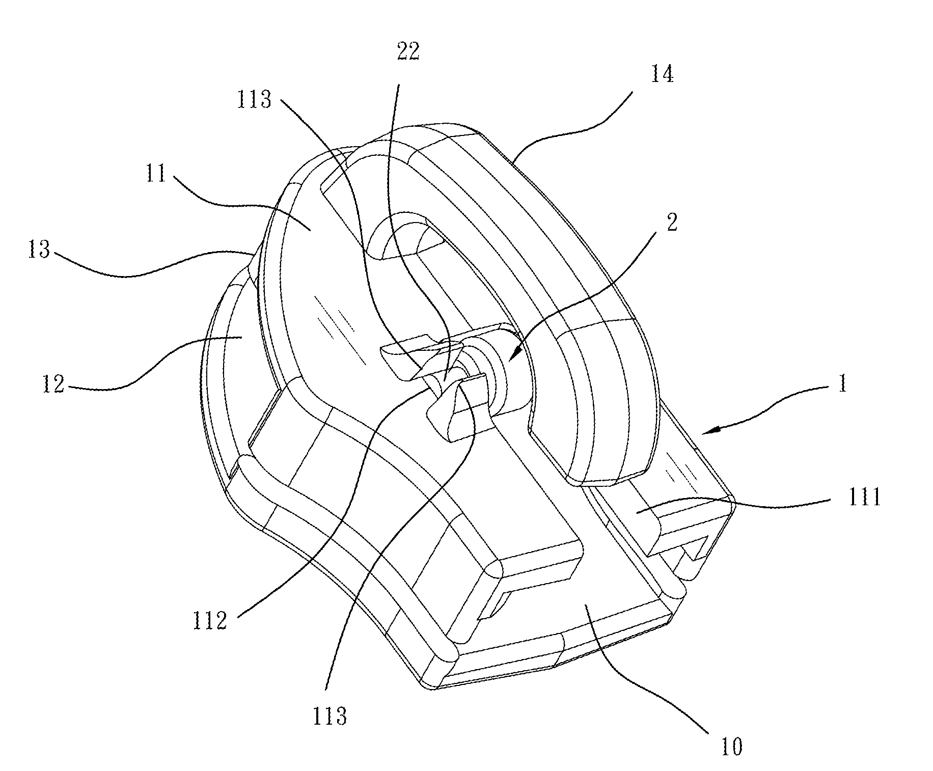
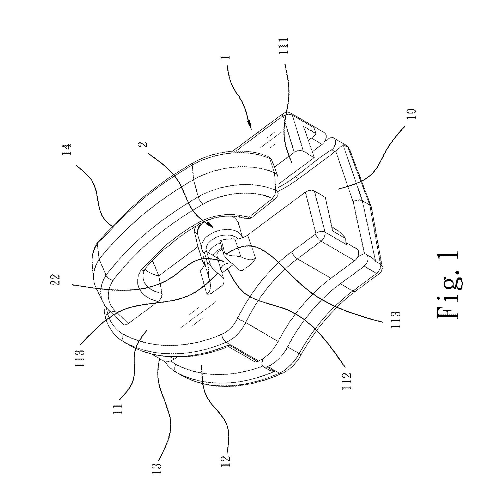
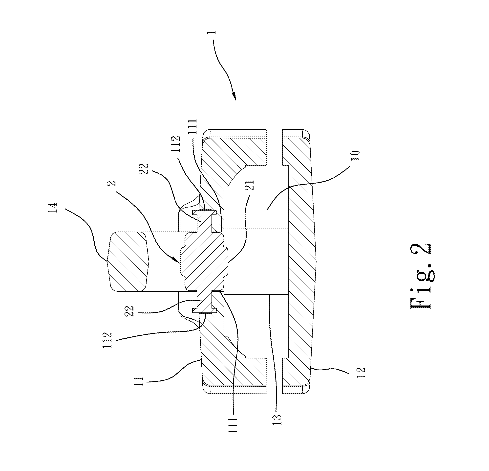
[0022]Referring to FIGS. 1-3, a roller zipper slide 1 in accordance with a first embodiment of the present invention employs a rolling contact technique to substitute for conventional surface friction designs, improving sliding mobility, reducing zipper teeth wear and prolonging zipper slide lifespan. As illustrated, the roller zipper slide 1 comprises a top slide body block 11, a bottom slide body block 12, a center block 13 connected between the top slide body block 11 and the bottom slide body block 12, an internal chamber 10 defined in between the top slide body block 11 and the bottom slide body block 12, and a crown 14 located on the top side of the top slide body block 11 for holding a pull tab (not shown).

[0023]The main features of the roller zipper slide 1 are outlined hereinafter.

[0024]The top slide body block 11 has a longitudinal slot 111 cut through the top and bottom sides thereof on the middle and two coupling grooves 112 located at two opposite lateral sides of the l...


PUM


Abstract

A roller zipper slide includes a slide body having a longitudinal slot on a top slide body block in communication with an internal chamber thereof and two coupling grooves located at two opposite lateral sides of the longitudinal slot. The roller zipper slide further includes a roller pivotally having two pivot pins respectively pivotally coupled to the coupling grooves and a bottom side thereof projecting into the internal chamber of the slide body right above the engaging position between the left and right series of teen of the zip fastener, thereby improving sliding mobility, reducing zipper teeth wear and prolonging zipper slide lifespan.

Description

BACKGROUND OF THE INVENTION[0001]1. Field of the Invention[0002]The present invention relates to zippers and more particularly, to a roller zipper slide for zip fastener, which employs a rolling contact technique to substitute for conventional surface friction designs, improving sliding mobility, reducing zipper teeth wear and prolonging zipper slide lifespan.[0003]2. Description of the Related Art[0004]The basic functional design of a zipper slide derives from rotating engagement between gears. The left series of teeth and right series of teeth of a zip fastener are regarded as two equal length flexible tooth bar. A zipper slide is movable by a pull tab to interlock or separate left and right series of teeth. If the protruding upper faces of the left series of teeth are stopped against the protruding upper faces of the right series of teeth during movement of the zipper slide to interlock the left and right series of teeth, much friction resistance will be produced, interfering sli...

Claims


Application Information

Patent Timeline
IPC IPC(8): A44B19/26
CPCA44B19/26Y10T24/2588Y10T24/2561
Inventor WANG, LIEN-CHOU
Owner WANG LIEN CHOU
Features
  • Generate Ideas
  • Intellectual Property
  • Life Sciences
  • Materials
  • Tech Scout
  • Unparalleled Data Quality
  • Higher Quality Content
  • 60% Fewer Hallucinations
Learn More