Pawl lock assembly system

a technology of pawl locks and assembly systems, applied in the direction of horological winding mechanisms, instruments, horological winding mechanisms, etc., can solve the problem of extremely delicate application of operations, and achieve the effect of increasing the thickness of respective members

Active Publication Date: 2012-07-26
NIVAROX FAR
View PDF30 Cites 14 Cited by
  • Summary
  • Abstract
  • Description
  • Claims
  • Application Information

AI Technical Summary

Benefits of technology

[0004]It is an object of the present invention to overcome all or part of the aforementioned drawbacks, by providing a securing system that does not increase the thickness of the respective members and can be applied to fragile materials.
[0006]The invention thus advantageously allows two elements to be secured to each other in the same plane, i.e. without any increase in the thickness of the elements, and without any plastic deformation which could, depending upon the nature of the materials, potentially be destructive.

Problems solved by technology

This type of operation requires extremely delicate application which makes it expensive.

Method used


Image

  • Pawl lock assembly system
  • Pawl lock assembly system
  • Pawl lock assembly system

Examples


first embodiment

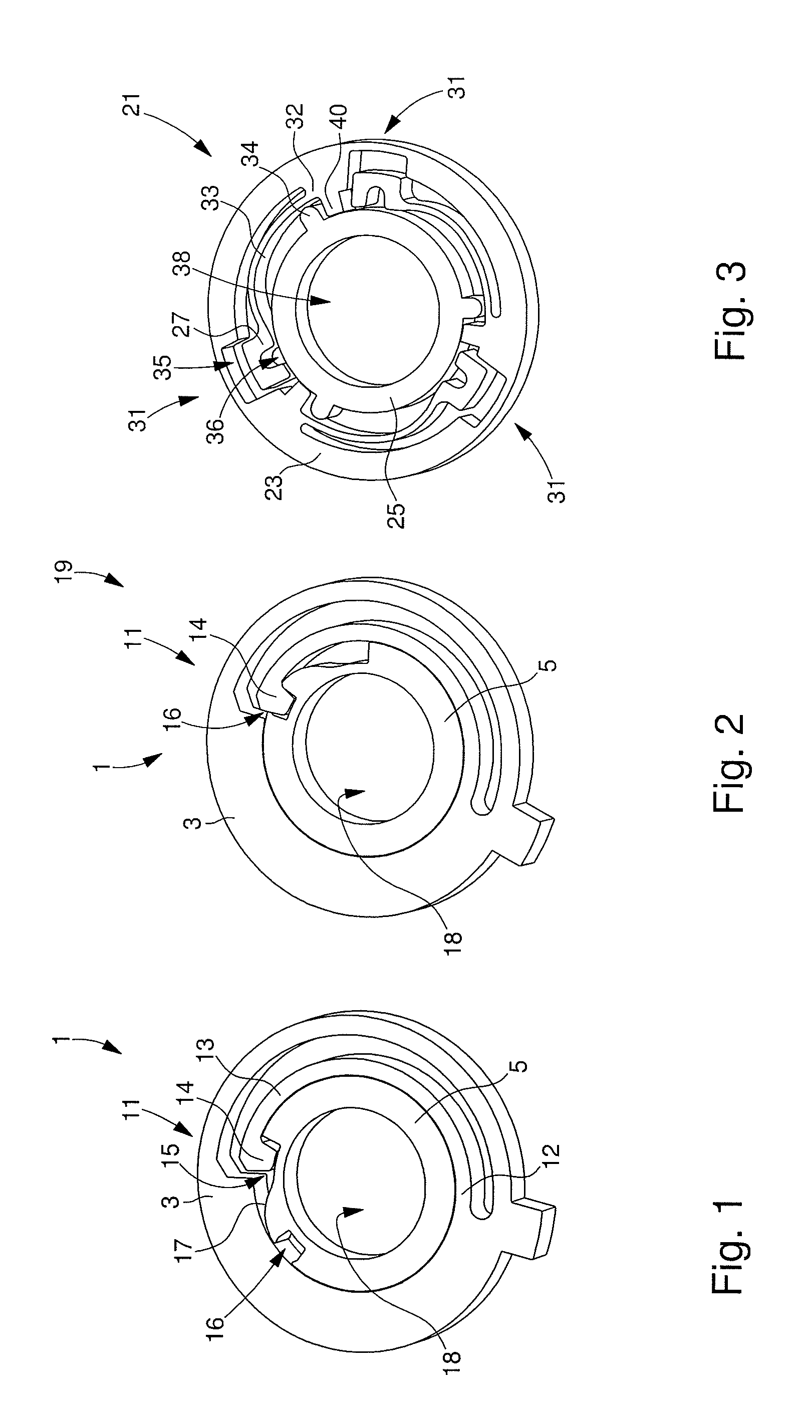
[0029]The system of securing the component and the part to each other will become clearer with reference to FIGS. 1 to 9, which show non-exhaustive embodiments and variants of the invention. illustrated in FIGS. 1 and 2, the securing system 1 includes a single pawl device 11. The pawl device 11 includes an arm 13 which is made in component 3. Arm 13 is thus elastically mounted on component 3 at a first end 12, so as to form a pawl as explained hereinafter. Finally, arm 13 includes at the second free end thereof, a tenon 14 which projects into the substantially central aperture 18 in component 3.

[0030]Pawl device 11 also includes a mortise 16, formed in part 5 and intended to cooperate with tenon 14 of arm 13, in order to secure component 3 to part 5. FIG. 1 also shows that part 5 has a recess 15, which flares gradually away from mortise 16 and which is intended to form a cam 17 for tenon 14.

[0031]The pawl device 11 of system 1 for securing component 3 to part 5 is activated as expl...

second embodiment

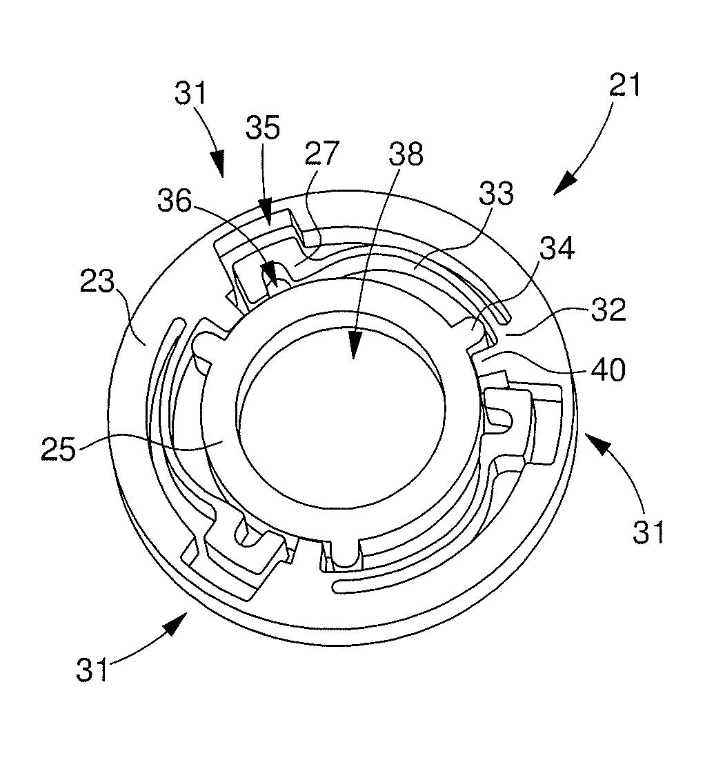
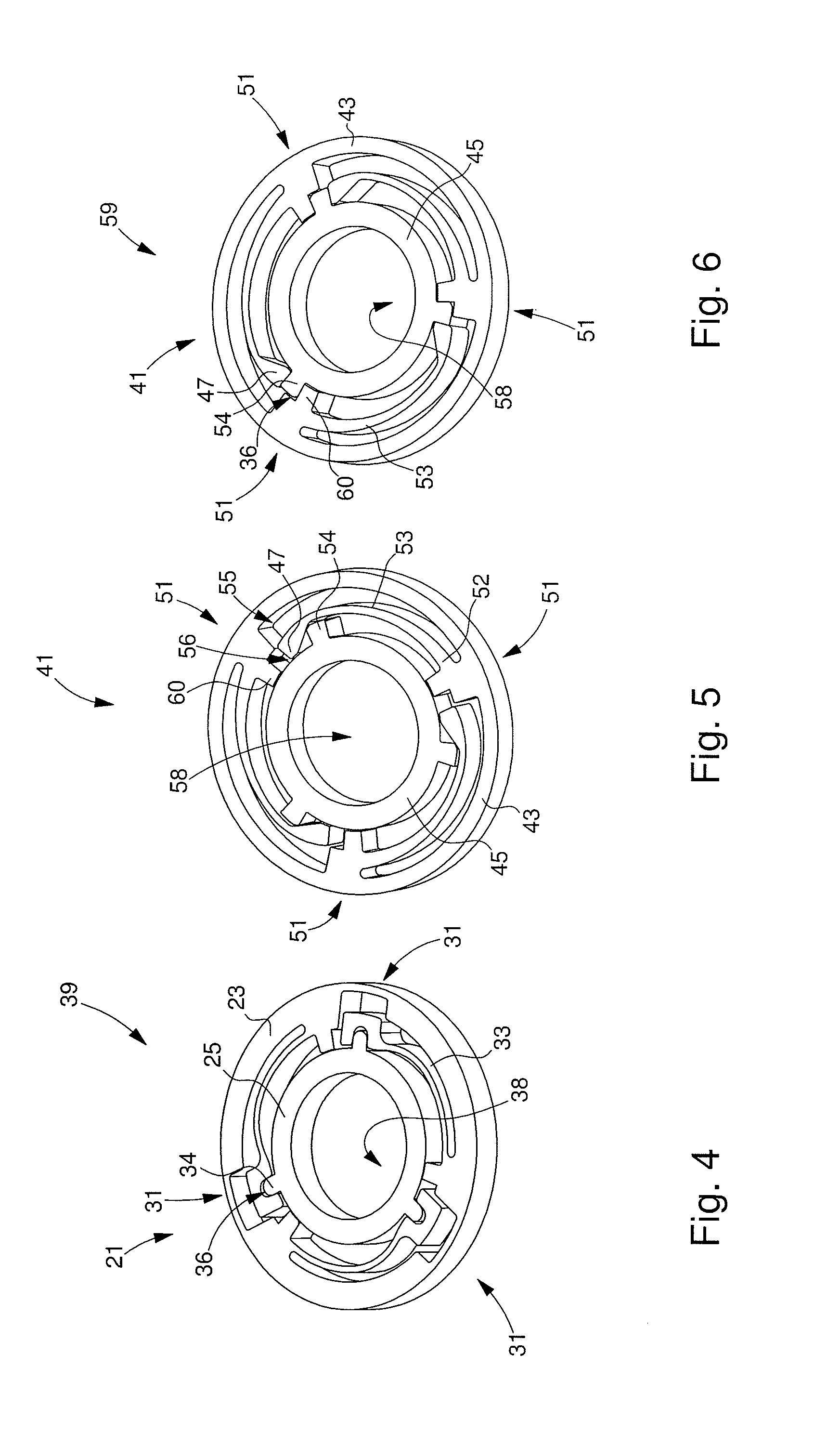
[0035] illustrated in FIGS. 3 and 4, the system 21 for securing component 23 and part 25 to each other includes three pawl devices 31. Each pawl device 31 includes a pawl arm 33, which is made in component 23. Arm 33 is thus elastically mounted on component 23 at a first end 32 so as to form a pawl, as explained hereinafter. Finally, at the second free end 27 thereof, arm 33 includes a mortise 36, which projects into the substantially central aperture 38 in component 23.

[0036]Each pawl device 31 also includes a tenon 34, formed in part 25 and intended to cooperate with the mortise 36 of an arm 33, in order to secure component 23 to part 25. FIG. 3 also shows that component 23 has a recess 35, which faces each free end 27 of an arm 33 including a mortise 36 and which is intended to create the clearance necessary for the elastic movement of said arm. Finally, for each pawl device 31, component 23 includes a stop member 40 for centring part 25 in aperture 38.

[0037]The pawl device 31 of...

third embodiment

[0041] illustrated in FIGS. 5 and 6, the system 41 for securing component 43 and part 45 to each other includes three pawl devices 51. Each pawl device 51 includes a pawl arm 53, which is made in component 43. Arm 53 is thus elastically mounted on component 43 at a first end 52 so as to form a pawl as explained hereinafter. Finally, at the second free end thereof, arm 53 includes a flange 47, intended to form a wall of mortise 56, which projects into the substantially central aperture 58 in component 43. Moreover, for each pawl device 51, component 43 includes a stop member 60, intended both to centre part 45 in aperture 58 and to form the rest of mortise 56, in cooperation with flange 47.

[0042]Each pawl device 51 also includes a tenon 54, formed in part 45 and intended to cooperate with mortise 56, formed by stop member 60 and flange 47, so as to secure component 43 to part 45. FIG. 5 also shows that component 43 has a recess 55, which faces each flange 47 of an arm 53 and which is...


PUM

PropertyMeasurementUnit
movementsaaaaaaaaaa
fragileaaaaaaaaaa
thicknessaaaaaaaaaa

Abstract

The invention relates to a method (19, 19′, 39, 39′, 59, 59′) of assembling a part (5, 5′, 25, 25′, 45, 45′) in the aperture (18, 18′, 38, 38′, 58, 58′) of a component (3, 3′, 23, 23′, 43, 43′). According to the invention, the assembly system (19, 19′, 39, 39′, 59, 59′) includes a system (1, 1′, 21, 21′, 41, 41′) of securing the component (3, 3′, 23, 23′, 43, 43′) and the part (5, 5′, 25, 25′, 45, 45′) to each other, which includes at least one pawl device (11, 11′, 31, 31′, 51, 51′) intended to make the component (3, 3′, 23, 23′, 43, 43′) and the part (5, 5′, 25, 25′, 45, 45′) move integrally with each other. The invention concerns the field of timepieces.

Description

[0001]This application claims priority from European Patent Application No. 11152202.5 filed Jan. 26, 2011, the entire disclosure of which is incorporated herein by reference.FIELD OF THE INVENTION[0002]The invention relates to a pawl lock assembly system and more specifically an assembly system of this type allowing the use of fragile material, i.e. which has no usable plastic domain.BACKGROUND OF THE INVENTION[0003]Current assemblies including a component made of fragile material such as silicon are generally secured by bonding. This type of operation requires extremely delicate application which makes it expensive.SUMMARY OF THE INVENTION[0004]It is an object of the present invention to overcome all or part of the aforementioned drawbacks, by providing a securing system that does not increase the thickness of the respective members and can be applied to fragile materials.[0005]The invention therefore relates to a system of assembling a part in the aperture of a component, charact...

Claims


Application Information

Patent Timeline
Patent Type & Authority Applications(United States)
IPC IPC(8): B23P19/04
CPCG04B11/028Y10T29/53613Y10T29/53687Y10T403/7061G04B13/02G04B13/022G04B15/14
Inventor CUSIN, PIERREQUEVAL, ARTHUR
Owner NIVAROX FAR
Why Eureka
Try Eureka