Apparatus and method for utilizing thermal energy

a technology of thermal energy and apparatus, applied in the direction of heating apparatus, fluid friction, lighting and heating, etc., can solve the problems of reducing the effectiveness of initial energy input ratio, method consumes a substantial amount of thermal and pumping energy, and requires a continuous motive for

Inactive Publication Date: 2012-07-26
HUDSON FISONIC CORP
View PDF8 Cites 30 Cited by
  • Summary
  • Abstract
  • Description
  • Claims
  • Application Information

AI Technical Summary

Problems solved by technology

This method consumes a substantial amount of thermal and pumping energy for heating and transportation of the liquid.
The disadvantage of jet-type devices is that jet-type devices use high level kinetic motive force to perform work, which degrades the outlet pressures, drastically reduces the effectiveness of initial energy input ratios and requires a continuous motive force.
Therefore these devices cannot be used to escalate pressure to a higher output level.
Further reduction of backpressure at this conditions leads to flashing of the water at the mixing chamber.

Method used


Image

  • Apparatus and method for utilizing thermal energy
  • Apparatus and method for utilizing thermal energy
  • Apparatus and method for utilizing thermal energy

Examples


Embodiment Construction

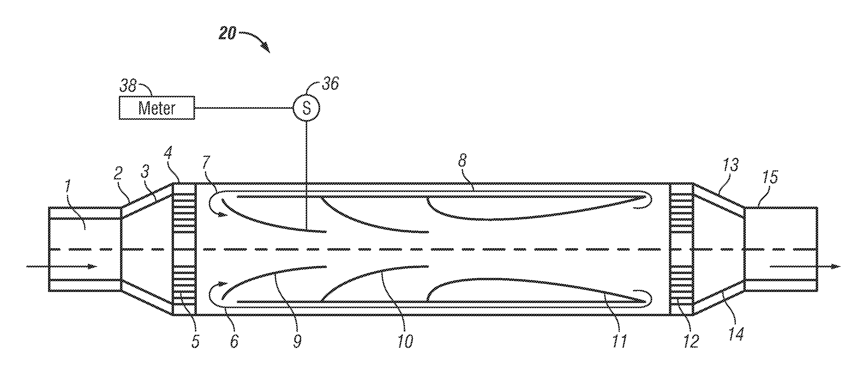
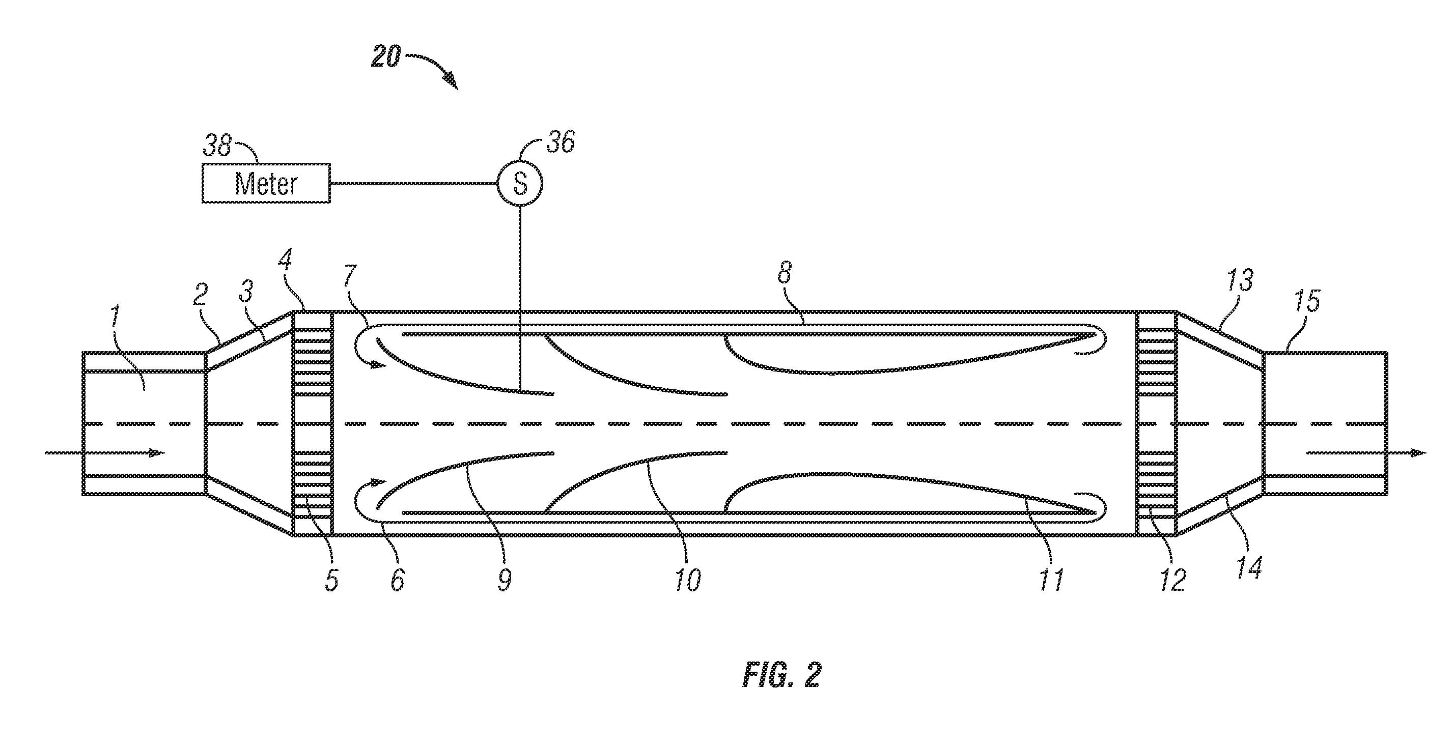
[0029]Embodiments of the present invention provide for a hypersonic kinetic energy harvester, heat exchanger, mixer, dozator, homogenizer, pasteurizer, de-superheater, pump, flow / energy meter, emulsifier, thruster, expander and hyper condensate recycler (collectively referred to as “FD device”). Embodiments of the present invention create conditions for thermal energy harvesting and substantial reduction of the thermal and pumping energy consumption by utilizing of the FD device. Embodiments of the invention provide for a FD device that converts the kinetic energy of the working fluid, supplied by the variable speed pump, into thermal and pumping energy, and provide reliable, stable and cavitation free operation of the system. This provides advantages in substantially reducing the energy consumption of the existing pump and the conventional thermal energy supply. Embodiments of the invention may also be equipped with a deaerator which thoroughly removes from the liquid the non-devic...


PUM


Abstract

An apparatus is provided having a heat generation device such as a boiler. A hypersonic energy harvester is provided having a first input and a second input. The first input and the second input are fluidly coupled to the heat generation device. A variable speed pump is fluidly coupled to supply liquid from the heat generation device to the hypersonic energy harvester. A deaerator is fluidly coupled to receive condensate from the hypersonic energy harvester.

Description

CROSS REFERENCE TO RELATED APPLICATIONSIf Applicable[0001]This application claims priority to U.S. Provisional Application Ser. No. 61 / 369,110 entitled “An Apparatus and Method for a Hypersonic Kinetic Energy Harvester, Mixer, Dozator, Homogenizer, Pasteurizer, Expander and Hyper Condensate Recycler” filed on Jul. 30, 2010 the contents of which are incorporated herein in their entirety.BACKGROUND OF THE INVENTION[0002]The invention relates to the field of thermal energy harvesting, mixing, vacuum and pumping technology, in which it is possible to organize the process of efficient thermal energy harvesting and create thrust and vacuum by utilizing the interparticle kinetic energy of the liquids in a closed or an open loop.[0003]Known method of heating liquids, includes an electric or steam driven pump, an indirect and direct contact heat exchangers and jet apparatuses supplied with thermal energy from boilers or district energy systems, where liquids are heated by steam or hot water ...

Claims


Application Information

Patent Timeline
Patent Type & Authority Applications(United States)
IPC IPC(8): E03B11/16
CPCF24J3/083Y02E10/125B01F5/0416F01K25/00B01F5/0428F24J3/006F28F13/06B01F5/0423Y10T137/85978F24V40/10F24T10/15Y02E10/10B01F25/3122B01F25/31233B01F25/31242
Inventor FISENKO, VLADIMIR V.KREMER, ROBERT
Owner HUDSON FISONIC CORP
Why Eureka
Try Eureka