Motor water-cooling structure and manufacturing method thereof

a technology of water cooling structure and motor, which is applied in the direction of cooling/ventilation arrangement, dynamo-electric components, light and heating apparatus, etc., can solve the problems of reducing the working affecting the efficiency of the motor, and the air cooling appears to have only limited effect in removing the produced heat from the motor, so as to reduce material, labor and time costs, and avoid the risk of water leakage , the effect of saving manufacturing costs

Inactive Publication Date: 2012-07-26
ASIA VITAL COMPONENTS SHENZHEN CO LTD
View PDF3 Cites 14 Cited by
  • Summary
  • Abstract
  • Description
  • Claims
  • Application Information

AI Technical Summary

Benefits of technology

[0019]With the present invention, the motor case for the motor water-cooling structure can be formed with one or more types of materials and the tube embedded in the motor case may can serve as a water passage, enabling the motor water-cooling structure to be manufactured at reduced material, labor and time costs, and to avoid the risk of water leakage. Therefore, the present invention has the following advantages: (1) saving the manufacturing cost; and (2) avoiding the risk of water leakage.

Problems solved by technology

When the produced heat is too high or largely accumulated in the motor, it would have adverse influence on the working efficiency of the motor.
In some worse conditions, the motor might become burnt out due to excessive heat produced by the stator or the rotor and accumulated in the motor.
However, air cooling appears to have only limited effect in removing the produced heat from the motor.
And, foreign matters, moisture and solutions tend to invasion into an interior of the motor via the holes formed on the motor case to cause damage to the stator and the rotor.
While the water cooling largely improves the heat dissipation of the motor, it also brings other problems to the motor.
That is, in the case the motor case and the enclosure are fabricated with insufficient precision, or in the event the material for forming the motor case and the enclosure become oxidized or corroded, cooling water flowing through the water passage tends to leak out of the groove.
Further, the forming of the groove on the motor case and the production of the enclosure with highly accurate dimensions are complicated and time consuming to inevitably increase the manufacturing cost of the motor.
In brief, the conventional water-cooling structure for motors has the following disadvantages: (1) requiring complicated fabricating processes; (2) requiring relatively high manufacturing costs; and (3) being subject to water leakage.

Method used


Image

  • Motor water-cooling structure and manufacturing method thereof
  • Motor water-cooling structure and manufacturing method thereof
  • Motor water-cooling structure and manufacturing method thereof

Examples


first embodiment

[0043]In a first step S1 according to the manufacturing method, a mold having a mold cavity and a tube are provided.

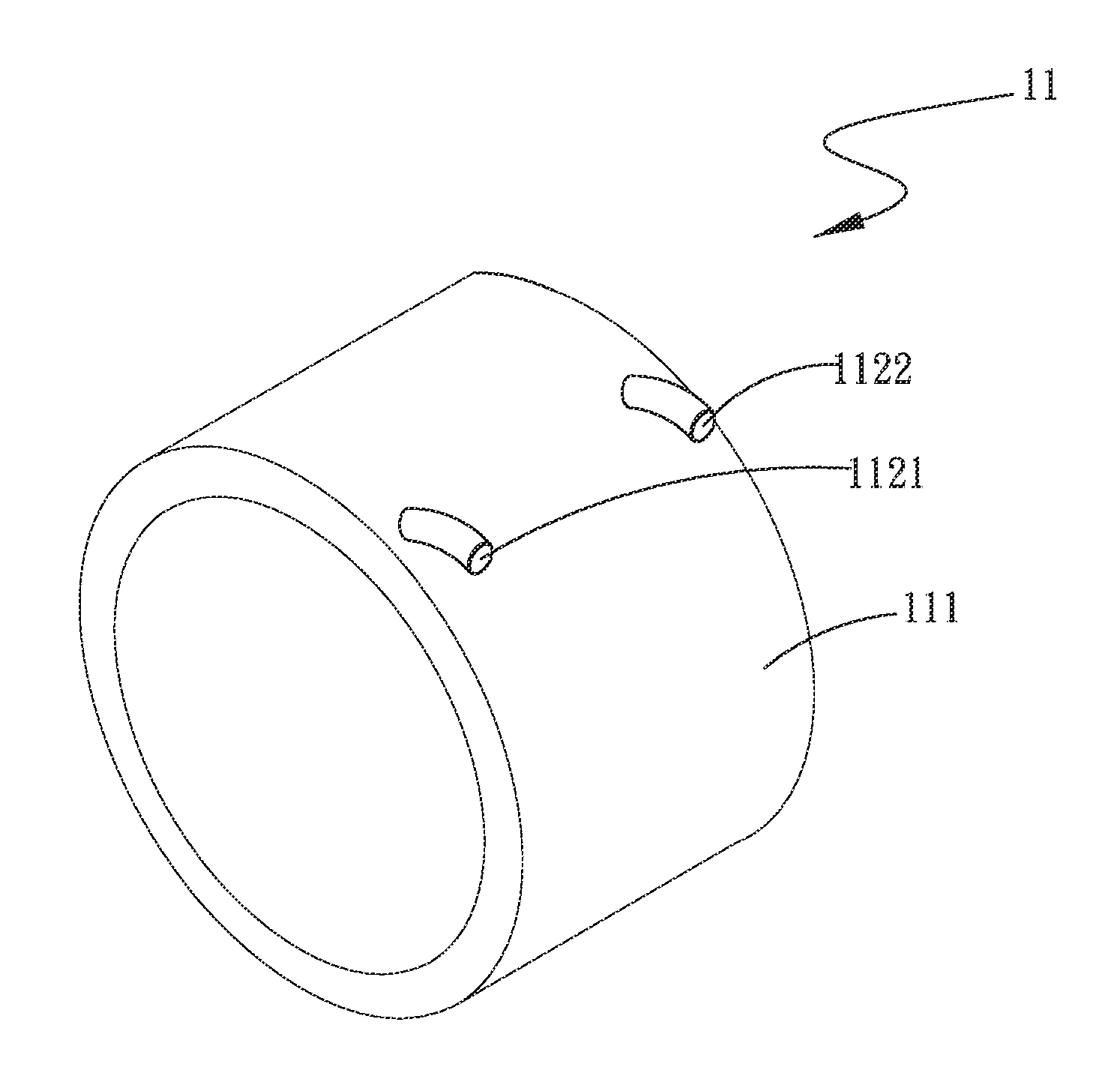
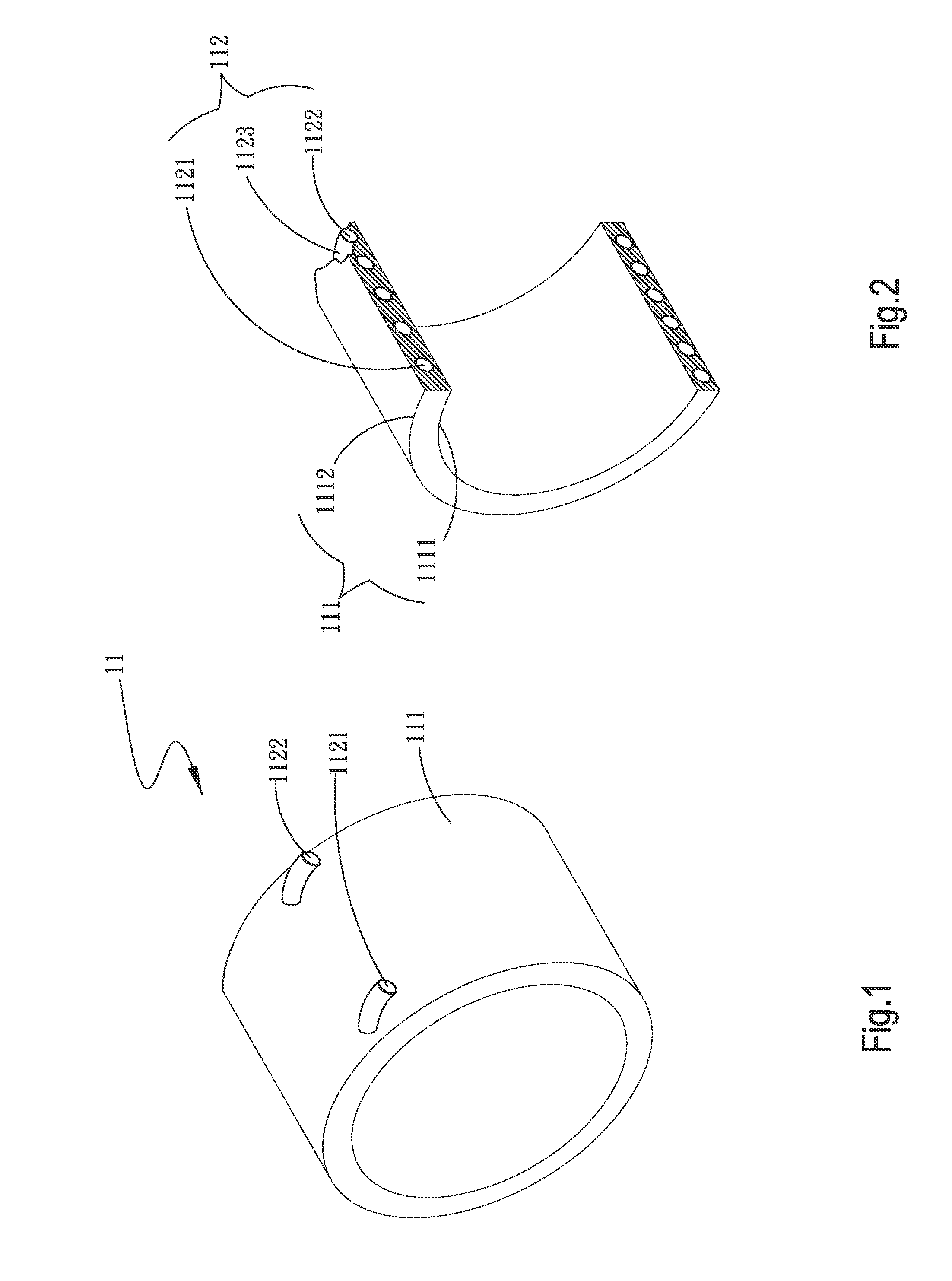
[0044]More specifically, as can be seen from FIGS. 6 and 7, a mold 2 having a mold cavity 21 is provided. The mold cavity 21 is dimensioned corresponding to a motor case that is to be formed, such as the motor case 11 shown in FIGS. 1 and 2. And, a tube, such as the tube 112 shown in FIGS. 1 and 2, is also provided.

[0045]Then, in a second step S2, the tube is positioned in the mold cavity of the mold, and a motor case is formed by pour molding to embed the tube therein.

[0046]More specifically, as can be seen from FIGS. 6 and 7, the tube 112 is positioned in the mold cavity 21 of the mold 2, and a motor case, e.g. the motor case 11, is formed by injection molding a plastic material or a metal material in the mold 2, so that the tube 112 is embedded in the motor case (e.g. the motor case 11) to serve as a flow passage in the molded motor case 11.

[0047]FIG. 5 also shows t...

third embodiment

[0052]In a first step X1 according to the manufacturing method, a mold having a mold cavity, a first motor case, and a tube are provided.

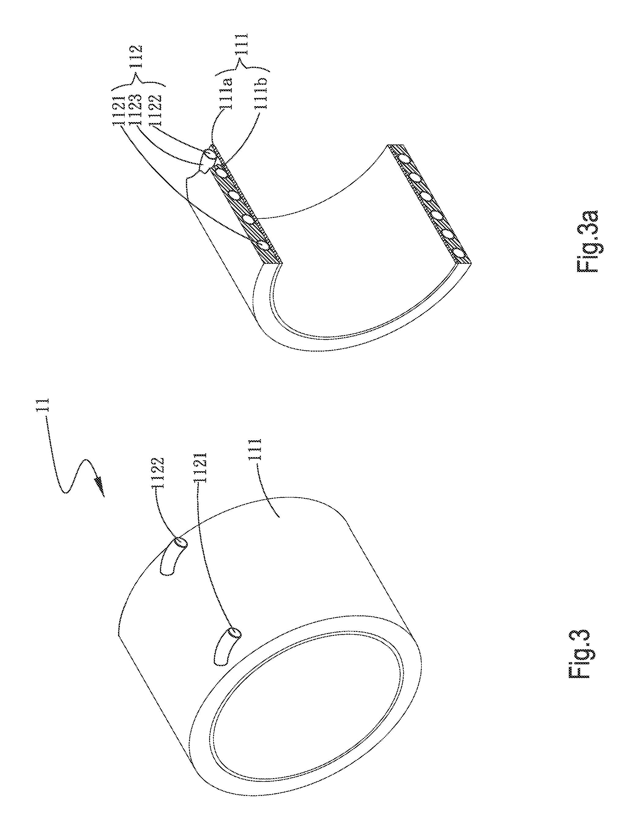
[0053]More specifically, as can be seen from FIGS. 11 and 12, a mold 2 having a mold cavity 21 is provided. And, a first motor case, such as the first part 111a shown in FIGS. 3 and 3a, and a tube, such as the tube 112 shown in FIGS. 3 and 3a, are also provided.

[0054]Then, in a second step X2, the tube is wound around an outer side of the first motor case, and the first motor case with the tube wound therearound is positioned in the mold cavity of the mold; and a second motor case is formed on an outer side of the first motor case to cover the first motor case and the tube, so that the second motor case, the first motor case and the tube form an integral body.

[0055]More specifically, as can be seen from FIGS. 11 and 12, the tube 112 is wound around the outer side of the first motor case (e.g. the first part 111a), and the first motor case with the ...

fifth embodiment

[0061]In a first step Y1 according to the manufacturing method, a mold having a mold cavity, a first motor case having a groove provided on an outer side thereof, and a tube are provided.

[0062]More specifically, as can be seen from FIGS. 16 and 17, a mold 2 having a mold cavity 21 is provided. And, a first motor case, such as the first part 111a shown in FIGS. 4 and 4a, having a groove (e.g. the groove 111c) provided on an outer side thereof, and a tube, such as the tube 112 shown in FIGS. 4 and 4a, are also provided.

[0063]Then, in a second step Y2, the tube is set in the groove on the outer side of the first motor case, and the first motor case with the tube set in the groove is positioned in the mold cavity of the mold; and a second motor case is formed on an outer side of the first motor case to cover the first motor case and the tube, so that the second motor case, the first motor case and the tube form an integral body.

[0064]More specifically, as can be seen from FIGS. 16 and 1...


PUM

PropertyMeasurementUnit
electric energyaaaaaaaaaa
heataaaaaaaaaa
dimensionsaaaaaaaaaa

Abstract

A motor water-cooling structure and a manufacturing method thereof are disclosed. The motor water-cooling structure includes a motor case having a wall portion and a tube. The tube is embedded in the wall portion to serve as a flow passage. To manufacture the motor water-cooling structure, the tube is positioned in a mold cavity of a mold, and the motor case is formed in the mold by pour molding to embed the tube therein, so that the motor case and the tube form an integral body. With the manufacturing method, the motor water-cooling structure can be formed with reduced material, labor and time to save the manufacturing costs, and the risk of water leakage can be avoided.

Description

[0001]This application claims the priority benefit of Taiwan patent application number 100102805 filed on Jan. 26, 2011.FIELD OF THE INVENTION[0002]The present invention relates to a motor water-cooling structure and a manufacturing method thereof; and more particularly to a motor water-cooling structure that includes a motor case formed of one or more types of materials, and a tube embedded in the motor case to serve as a water passage, so as to reduce the manufacturing cost and avoid the risk of water leakage.BACKGROUND OF THE INVENTION[0003]A motor is a prerequisite machine for energy conversion. There are motors that convert electric energy into kinetic energy, such as the motors for fans, water pumps and the like. There are also motors that convert kinetic energy into electric energy, such as power generators. Most of the currently available motors are used for the above-mentioned applications. Either the motors for converting electric energy into kinetic energy or the motors f...

Claims


Application Information

Patent Timeline
Patent Type & Authority Applications(United States)
IPC IPC(8): F28F21/00B29C39/10B29C45/14
CPCB29C39/10B29C45/14065H02K15/14H02K5/20H02K9/19F28F21/00H02K5/203
Inventor LEE, SUNG-WEI
Owner ASIA VITAL COMPONENTS SHENZHEN CO LTD
Why Eureka
Try Eureka