Combination computed and direct radiography system and method

a radiography system and computed technology, applied in the field of radiography systems, can solve the problems of increasing the time before an image is actually created by the cr system, the overall size of the system, the time and cost associated with repairing and maintenance, and the system does not use a cassette containing imaging plates, so as to prevent further loading of imaging plates

Inactive Publication Date: 2012-07-26
ICRCO
View PDF1 Cites 3 Cited by
  • Summary
  • Abstract
  • Description
  • Claims
  • Application Information

AI Technical Summary

Benefits of technology

[0015]The fixed imaging plate may also be moved into a second position through a series of rotating members and linkages coupling the fixed imaging plate to the frame assembly and moving it relative to the scanning assembly. Prior to moving into the second position, the cassette carriage may be locked to prevent further loading of imaging plates. In the second position, the radiography device operates and functions as a DR system by utilizing the fixed imaging plate within the housing to store and then acquire images. In this mode of operation, the x-ray images arc taken over the desired object or patient and the radiography device, which houses the fixed imaging plate. There is no need to remove the imaging plate from the carriage to take new images. In this second position, the fixed imaging plate is advantageously moved from the first retracted position within the exterior housing to the second position adjacent to the scanning assembly to allow proper scanning and image acquisition. In yet another embodiment, the imaging plate may be moved into either the first or second position from the cassette carriage assembly.

Problems solved by technology

Commonly cited drawbacks include the need to typically handle the imaging plate within a cassette, the burden of moving the imaging plate cassette from the x-ray exposure position to the CR system and then scanning it to obtain the desired image.
In addition to requiring additional handling, these efforts increase the time before an image is actually created by the CR system.
Other cited drawbacks include the overall size of the system, cost and complexity of the devices, including the time and costs associated with repairing and maintenance.
These systems, however, do not use cassettes containing imaging plates.

Method used


Image

  • Combination computed and direct radiography system and method
  • Combination computed and direct radiography system and method
  • Combination computed and direct radiography system and method

Examples


Embodiment Construction

[0034]Existing computed radiography (“CR”) designs providing quality imaging characteristics and methods arc complex and expensive to manufacture, maintain and repair. The problems of expense and complexity of manufacture, maintenance and repair are generally deemed worse when associated with existing direct radiography (“DR”) designs. In addition, downtown costs associated with maintaining and servicing current CR and DR devices, can be critical with such existing designs.

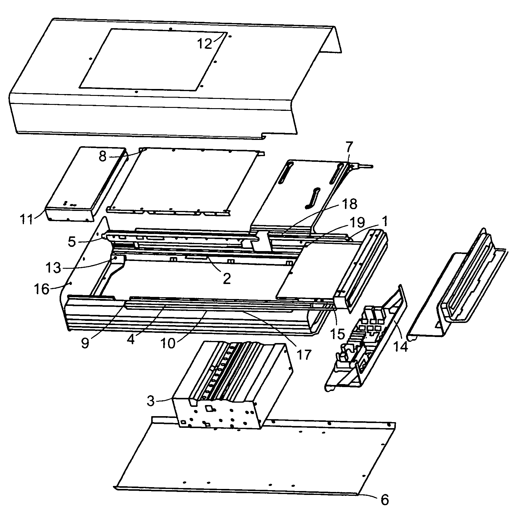
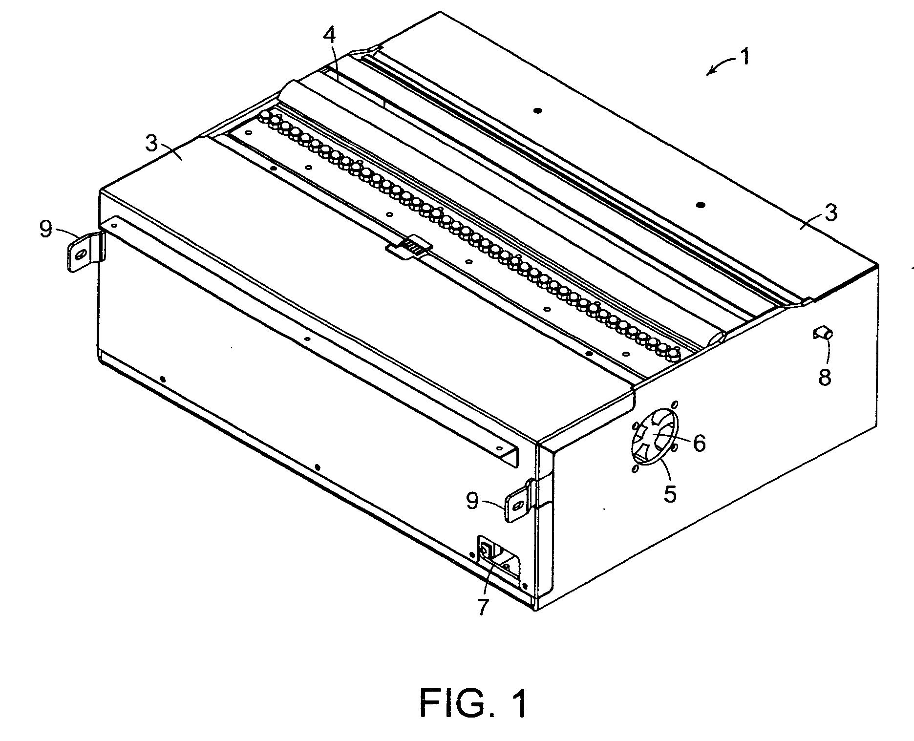
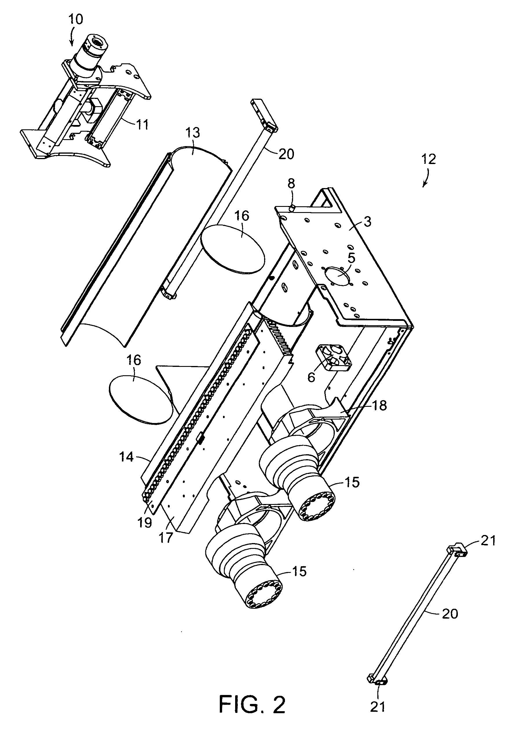
[0035]In the present design and methods, novel modular components and assemblies arc provided that find application in both CR and fixed imaging plate scanning devices, including DR applications. The novel design and application of these modular systems and components minimize or avoid altogether, the high costs and delays previously associated with repairs and maintenance. For example, the use of the presently designed modular systems generally eliminates the requirement that the radiology device be shipped back ...


PUM


Abstract

A scanning apparatus that can operate as both a computed and direct style radiography device. In the computed radiography mode, an internal imaging plate is removed or maintained inwardly within the housing assembly to allow a cassette handling mechanism holding a removable imaging plate to pass adjacent the scanning head. In the direct radiography mode, the cassette handling mechanism is retracted and the internal imaging plate is moved outward from the within the housing such that it is located adjacent the reading slot of the scan head assembly. In both modes of operation, the imaging plate being used is maintained adjacent the scan head while the scan head and imaging plate surface are moved relative to each other allowing the scanning and acquisition of the image data stored on the plate.

Description

CROSS REFERENCE TO RELATED APPLICATIONS [0001]This application claims priority to and the benefit of U.S. Provisional Application No. 61 / 417,423 filed, Nov. 27, 2010, entitled, Combination Computed anti Direct Radiography System And Method,BACKGROUND [0002]1. Field of the Invention[0003]The present invention relates generally to radiography systems and more specifically to a combination modular computed and direct radiography system and method.[0004]2. Background of the Invention[0005]Computed radiography (“CR”) systems generate a digital image of an x-ray by scanning an x-ray storage phosphor imaging plate that has been exposed to x-ray energy, usually while at least partially housed in a cassette. The re-useable imaging plate replaces the need for previously conventional x-ray film. The imaging plate is typically coated with photostimulable storage phosphors allowing it to store the energy received from the x-ray irradiation. The cassette encases the imaging plate and prevent expo...

Claims


Application Information

Patent Timeline
Patent Type & Authority Applications(United States)
IPC IPC(8): G21K4/00
CPCG03B42/04G03B42/045A61B6/4283A61B6/032A61B6/4208G03B42/08A61B6/035G03B42/02H04N5/32
Inventor NEUSHUL, STEPHEN
Owner ICRCO
Why Eureka
Try Eureka