
Multi-lamp driving system

a driving system and multi-lamp technology, applied in the direction of electric variable regulation, process and machine control, instruments, etc., can solve the problem of circuits mis-comparison of detected signals and predetermined reference voltages

Inactive Publication Date: 2012-07-26
AMPOWER TECH CO LTD
View PDF4 Cites 3 Cited by
  • Summary
  • Abstract
  • Description
  • Claims
  • Application Information

AI Technical Summary

Benefits of technology

[0023]The multi-lamp driving systems 10 and 20 dynamically retrieves the highest current signal and the lowest current signal to compare to determine if there is abnormity, replacing with comparison with a fixed reference voltage. Thus, when environment temperature and parameters of the lamps L1 and L2 change, the highest current signal and the lowest current signal change correspondingly, which avoids influence on abnormity determination and misact.

Problems solved by technology

However, because the predetermined reference voltage is a fixed voltage, the circuit may mis-compare the detected signals with the predetermined reference voltage due to change of environment temperature and lamp parameters.

Method used


Image

  • Multi-lamp driving system
  • Multi-lamp driving system
  • Multi-lamp driving system

Examples


first embodiment

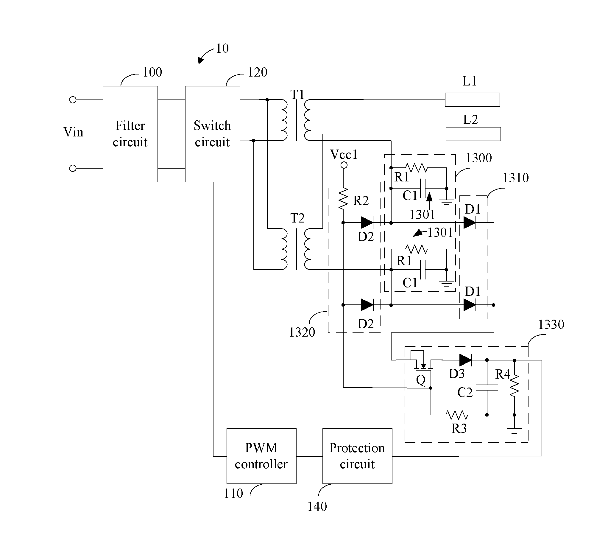
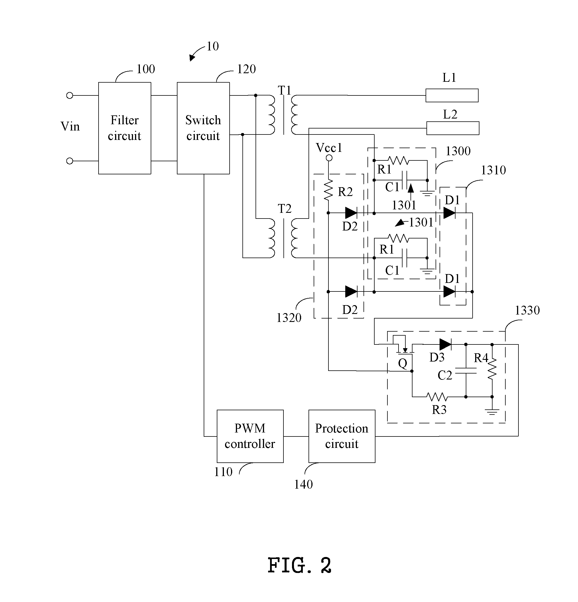
[0014]FIG. 2 is a circuit diagram of the multi-lamp driving system 10 as disclosed. In one embodiment, the signal converting circuit 1300 includes a plurality of signal converting units 1301, and the plurality of signal converting units 1301 are correspondingly connected to the low voltage terminals of the secondary windings of the transformers T1 and T2. That is, a first signal converting unit 1301 is connected to the low voltage terminal of the secondary winding of the transformer T1, and a second signal converting unit 1301 is connected to the low voltage terminal of the secondary winding of the transformer T2. Each of the plurality of signal converting units 1301 converts the current signals flowing through corresponding lamps L1 and L2 into the voltage signals, and includes a first resistor R1 and a first capacitor C1. The first resistor R1 is connected between the low voltage terminal of the secondary winding of the corresponding transformer and the ground. The first capacitor...

second embodiment

[0022]FIG. 3 is a circuit diagram of a multi-lamp driving system 20 as disclosed. The multi-lamp driving system 20 is similar to the multi-lamp driving system 10 except that a structure of a comparison circuit 1330A is different from that of the comparison circuit 1330, therefore, descriptions of other same structures are omitted here. The comparison circuit 1330A includes a comparator 1331, the third diode D3, the second capacitor C2, the fourth resistor R4, and a fifth resistor R5. A non-inverting input of the comparator 1331 is connected to the cathodes of the plurality of first diodes D1, an inverting input of the comparator 1331 is connected to the anodes of the plurality of second diodes D2, and an output of the comparator 1331 is connected to the anode of the third diode D3. One end of the fifth resistor R5 is connected to the output of the comparator 1331, and another end of the fifth resistor R5 receives a second reference voltage. Connections and functions of the third dio...


PUM


Abstract

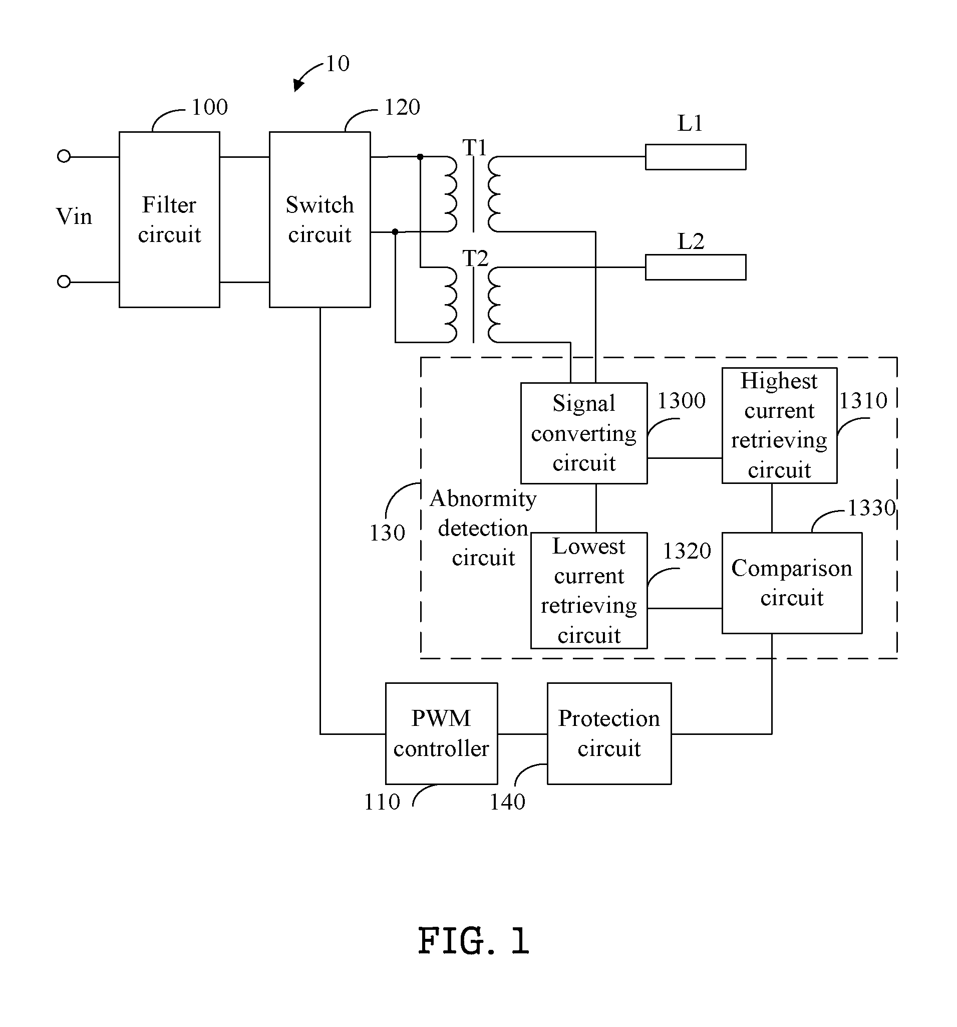
A multi-lamp driving system includes a filter circuit, a switch circuit, a pulse width modulation (PWM) controller, a protection circuit, transformers, and an abnormity detection circuit. Primary windings of the transformers are connected to the switch circuit in parallel, and high voltage terminals of secondary windings of the transformers are connected to lamps respectively. The abnormity detection circuit converts current signals flowing through the lamps into voltage signals, and retrieves highest and lowest voltage signals corresponding to highest and lowest current signal respectively. Then the abnormity detection circuit determines if a difference between the highest voltage signal and the lowest voltage signal exceeds a predetermined value, and generates a trigger signal if the difference between the highest and lowest voltage signals exceeds the predetermined value. The protection circuit receives the trigger signal, and controls the PWM controller to stop outputting PWM signals to the switch circuit.

Description

BACKGROUND[0001]1. Technical Field[0002]The disclosure relates to backlight driving systems, and particularly to a multi-lamp driving system.[0003]2. Description of Related Art[0004]Cold cathode fluorescent lamps (CCFL) are usually used for a backlight of a liquid crystal display. An inverter converts direct current power into alternating current power to provide proper driving power to light the CCFL. There is a circuit in the inverter that is used to detect abnormity and to protect the CCFLs and the inverter. Usually, the circuit compares the detected signals with a predetermined reference voltage to determine if acts to protect the CCFLs and the inverter. However, because the predetermined reference voltage is a fixed voltage, the circuit may mis-compare the detected signals with the predetermined reference voltage due to change of environment temperature and lamp parameters.BRIEF DESCRIPTION OF THE DRAWINGS[0005]FIG. 1 is a schematic diagram of one embodiment of a multi-lamp dri...

Claims


Application Information

Patent Timeline
Patent Type & Authority Applications(United States)
IPC IPC(8): H05B37/02
CPCY02B20/186H05B41/2855Y02B20/00
Inventor HO, CHI-HSIENCHENG, CHIN-PO
Owner AMPOWER TECH CO LTD
Learn More