Tactile display and cad system
a display and cad technology, applied in the field of tactile display, can solve the problems of not providing the fine relief on the object surface in an easy to understand manner, and achieve the effect of finely modifying the surface shape data
- Summary
- Abstract
- Description
- Claims
- Application Information
AI Technical Summary
Benefits of technology
Problems solved by technology
Method used
Image
Examples
embodiment 1
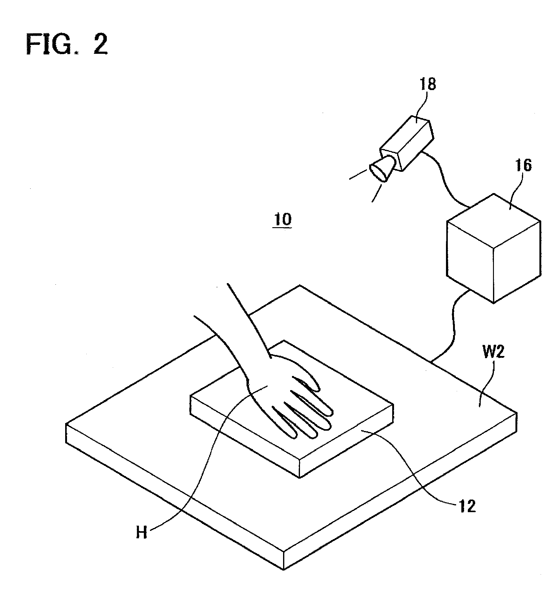
[0037]FIG. 2 shows a schematic perspective view of a tactile display 10 in Embodiment 1.
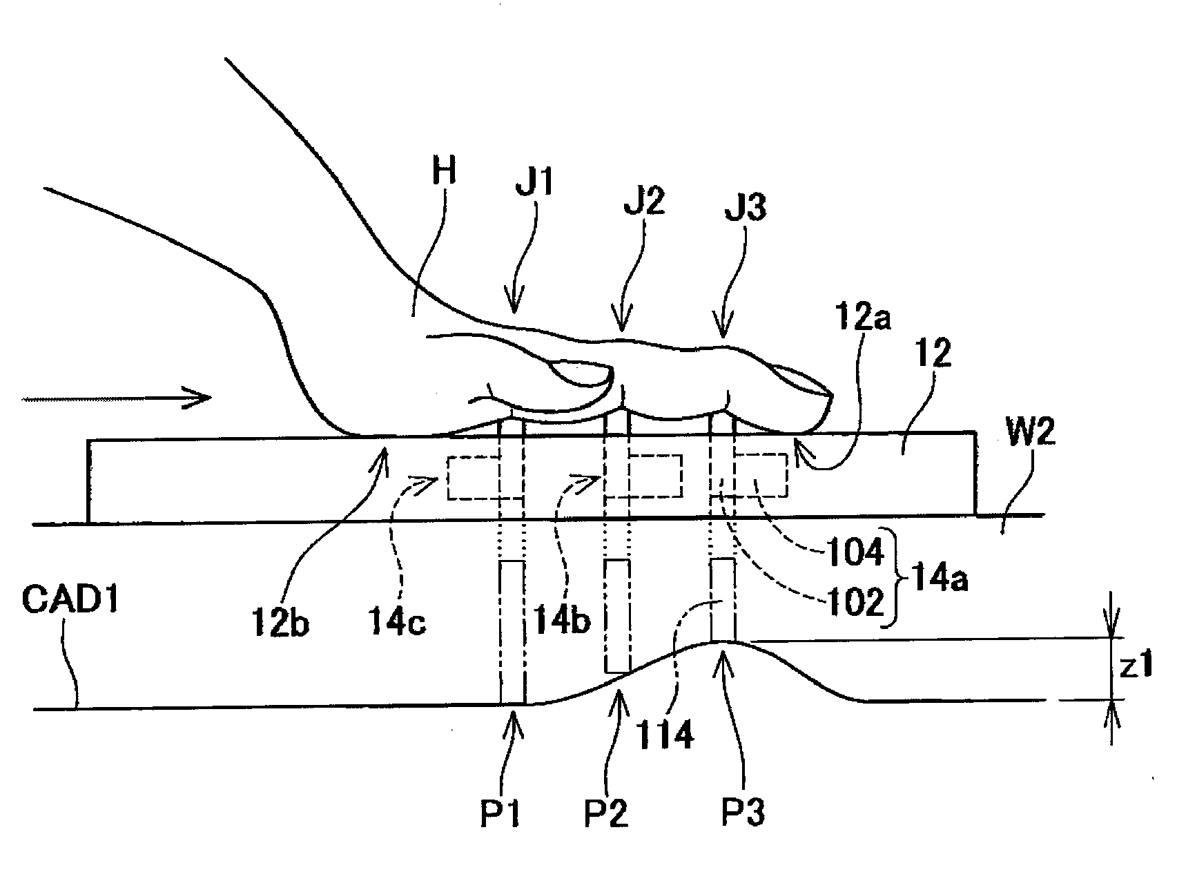
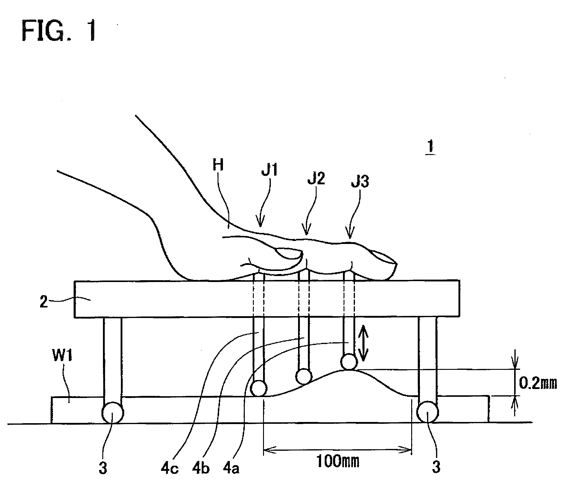
[0038]FIG. 3 shows a schematic side view of a tactile device 12. The tactile display 10 comprises the tactile device 12, a controller 16, and an image processing device 18. The tactile device 12 is wearable on a human palm. More specifically, the tactile device 12 can be moved on a surface of an object W2 with the person hand placed on the tactile device 12. A mark H in FIG. 2 and FIG. 3 indicates the person hand. The image processing device 18 detects a movement of the tactile device 12 with a camera. More specifically, the image processing device 18 detects a relative movement of the tactile device 12 to the object W2 from an image taken. At the same time, the image processing device 18 measures a position of the object W2 as well. The image processing device 18 corresponds to a sensor which detects the movement of the tactile device 12. Referring to an image processing algorithm for detecting ...
embodiment 2
[0048]A tactile display in Embodiment 2 will be described. The tactile display in Embodiment 2 comprises a tactile device 22 shown in FIG. 4 instead of the tactile device 12 in Embodiment 1. The tactile device 22 comprises nine stimulators 24. Each of the stimulators 24 comprises an actuator (not shown) as well as the stimulator 14 in Embodiment 1, and the upper end of the actuator moves up and down. Two adjacent stimulators among 9 stimulators 24 are arranged so that they face to positions of adjacent finger joints when a person places one's palm on the tactile device 22. When the person places the palm on the tactile device 22, each of the nine stimulators 24 faces toward a total of nine joints of the middle finger, the index finger, and the annular finger. Three virtual lines G in FIG. 4 schematically represent the middle finger, the index finger, and the annular finger of when the tactile device 22 is worn on the hand, respectively. Two adjacent stimulators are arranged, separat...
embodiment 3
[0050]Embodiment 3 will be described, referring to FIG. 6 and FIG. 7. A tactile display in Embodiment 3 comprises a glove-type tactile device 32. The tactile display in Embodiment 3 comprises the image processing device 18 and the controller 16 in Embodiment 1. The description for them will be omitted. FIG. 6 shows a schematic perspective view of the tactile device 32. The tactile device 32 comprises a plurality of ring-shaped stimulators 34. As shown in FIG. 6, each of the stimulators 34 is arranged at a position corresponding to each joint position of fingers when the person wears the tactile device 32. A schematic enlarged front view of the stimulator 34 is shown in FIG. 7. As shown in FIG. 7, the stimulator 34 has an electrode 134. The electrode 134 faces toward the finger joint position of the palmar-side skin when the person wears the tactile device 32. Note that although the electrode 134 and the finger F are depicted apart in FIG. 7, the electrode 134 makes contact with the ...
PUM
 Abstract
Description
Claims
Application Information
 - R&D
- Intellectual Property
- Life Sciences
- Materials
- Tech Scout
- Unparalleled Data Quality
- Higher Quality Content
- 60% Fewer Hallucinations
Browse by: Latest US Patents, China's latest patents, Technical Efficacy Thesaurus, Application Domain, Technology Topic, Popular Technical Reports.
© 2025 PatSnap. All rights reserved.Legal|Privacy policy|Modern Slavery Act Transparency Statement|Sitemap|About US| Contact US: help@patsnap.com


